
Textile cloth winding device with dust removal function

A rolling device and cloth technology, applied in textiles and papermaking, winding strips, transportation and packaging, etc., can solve the problems of cloth not having the function of dust removal, affecting product appearance, unfavorable processing, etc., and achieve a good user experience , Simple structure, stable transmission effect

Inactive Publication Date: 2021-02-26
安徽美诗兰科技有限公司
View PDF0 Cites 2 Cited by
  • Summary
  • Abstract
  • Description
  • Claims
  • Application Information

AI Technical Summary

Problems solved by technology

After the textile cloth is processed, the cloth will be wound and stored, so a winding device will be used. At present, the existing winding devices on the market do not have the function of dust removal when the cloth is wound. There will be dust attached to the surface, if it is not cleaned, it will not only affect the appearance of the product, but also not conducive to the processing of the subsequent process.

Method used


Image

  • Textile cloth winding device with dust removal function
  • Textile cloth winding device with dust removal function
  • Textile cloth winding device with dust removal function

Examples


Embodiment 1

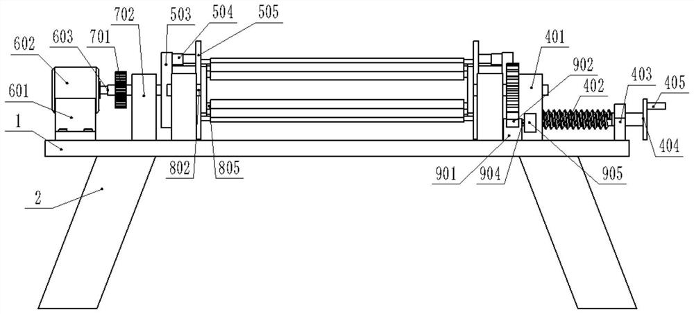
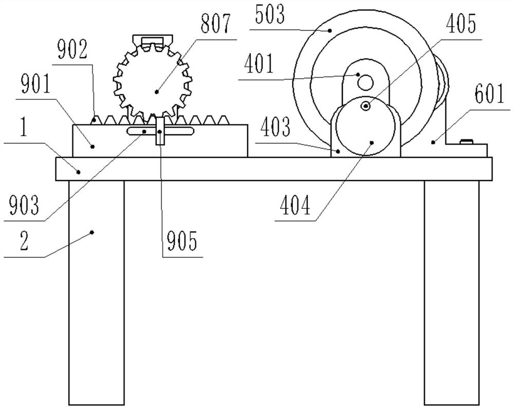
[0023] Example 1: Please refer to Figure 1-4 , a cloth winding device with dust removal function for textile use, including a workbench 1, support legs 2 are fixedly connected to the bottom of the workbench 1, front, rear, left, and right, and a chute 3 is opened on the right side of the upper middle part of the workbench 1 ;

[0024] The chute 3 is slidably connected with the installation mechanism 4. When in use, the handle 405 is turned, which then drives the turntable 404 to rotate, and then the screw rod 402 is turned, and then the sliding block 401 is moved, and then the right horizontal axis 501 is aligned with the left horizontal axis. 501 is disengaged, the cloth tube is sleeved on the surface of the reel 502, and the handle 405 is turned to restore the reel 502 on both sides to its original position;

[0025] The installation mechanism 4 is rotatably connected with the winding mechanism 5, and the hydraulic telescopic shaft 504 is opened, so that the pressure plate...

Embodiment 2

[0036]Embodiment 2: This embodiment is a further improvement of the previous embodiment: the connection method between the limiting block 901 and the workbench 1 is welding.

[0037] The working principle of the present invention is: turn the handle 405 during use, and then drive the turntable 404 to rotate, and then make the screw rod 402 rotate, and then make the sliding block 401 move, and then make the right horizontal axis 501 and the left horizontal axis 501 separate, and the cloth The tube is sleeved on the surface of the reel 502, and the handle 405 is turned to return the reel 502 on both sides to its original position; the hydraulic telescopic shaft 504 is opened to move the pressure plate 505 relatively, and then the two ends of the cloth tube are pressed tightly, and the cloth One side passes through the dust suction cylinder 806 and is fixed on the cloth cylinder sleeved on the surface of the winding cylinder 502, pushing the push plate 905 and then moving the rack...


PUM


Abstract

The invention discloses a textile cloth winding device with a dust removal function, and relates to the textile field. The textile cloth winding device with the dust removal function comprises a workbench, wherein supporting legs are fixedly connected to the lower side of the workbench in a front-back and left-right symmetry mode. A sliding groove is formed in the right side of the portion, on therear side of the middle, of the upper side of the workbench. The sliding groove is connected with a mounting mechanism in a sliding manner, and the mounting mechanism is rotationally connected with awinding mechanism. The left end of the portion on the rear side of the middle of the upper side of the workbench is fixedly connected with a driving mechanism, the driving mechanism is engaged with atransmission mechanism, and the transmission mechanism is fixedly connected with the winding mechanism. A dust removal mechanism is fixedly connected with the front end of the middle of the upper side of the workbench and is engaged with an adjusting mechanism. The textile cloth winding device with the dust removal function is simple in structure, convenient to use, and good in use experience.

Description

technical field [0001] The invention relates to the field of textiles, in particular to a cloth winding device for textiles with dust removal function. Background technique [0002] The original meaning of textile is taken from the general term of spinning and weaving, but with the continuous development and improvement of the textile knowledge system and subject system, especially after the emergence of non-woven textile materials and three-dimensional composite weaving technologies, the current textile is not only a traditional Hand spinning and weaving also include garment, industrial and decorative textiles produced by non-woven technology, modern three-dimensional weaving technology, and modern electrostatic nano-netting technology. After the textile cloth is processed, the cloth will be wound and stored, so a winding device will be used. At present, the existing winding devices on the market do not have the function of dust removal when the cloth is wound. There will ...

Claims


Application Information

Patent Timeline
Patent Type & Authority Applications(China)
IPC IPC(8): B65H18/10B65H18/02D06G1/00
CPCB65H18/028B65H18/10B65H2701/174B65H2701/19D06G1/00
Inventor 汪娜
Owner 安徽美诗兰科技有限公司
Learn More