
Automatic die cutting mechanism

A die-cutting knife and frame technology, applied in metal processing, etc., can solve the problems of lack of precision, high cost, cumbersome die-cutting steps, etc., and achieve the effect of improving the adhesion firmness, simple operation mode, and realizing the effect of speed regulation

Inactive Publication Date: 2021-02-26
BROTECH GRAPHIC
View PDF0 Cites 0 Cited by
  • Summary
  • Abstract
  • Description
  • Claims
  • Application Information

AI Technical Summary

Problems solved by technology

[0002] At present, die-cutting equipment is mostly used in the die-cutting process of substrates. When the die-cutting equipment is working, it needs to use molds to die-cut a large number of products. Different patterns need to use different molds, so there are cumbersome die-cutting steps and high costs. ; and most die-cutting equipment is relatively cumbersome in adjusting the transmission speed of the substrate, and lacks precision, which greatly affects the quality of die-cutting

Method used


Image

  • Automatic die cutting mechanism
  • Automatic die cutting mechanism
  • Automatic die cutting mechanism

Examples


Embodiment Construction

[0023] It should be understood that the specific embodiments described here are only used to explain the present invention, not to limit the present invention. It should be noted that relative terms such as "first", "second" and so on may be used to describe various components, but these terms do not limit the components. These terms are only used to distinguish one component from another. For example, without departing from the scope of the present invention, a first component may be called a second component, and a second component may similarly be called a first component. The term "and / or" refers to any one or more combination of related items and described items.

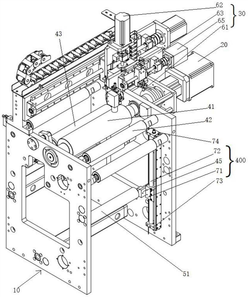
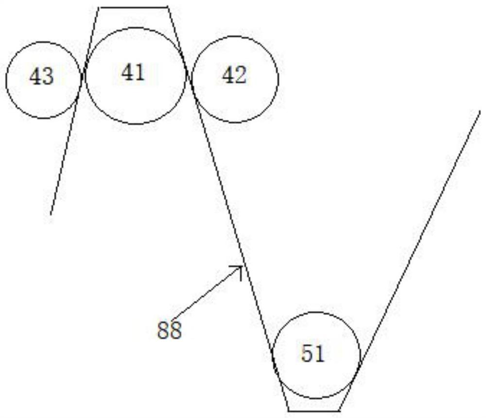
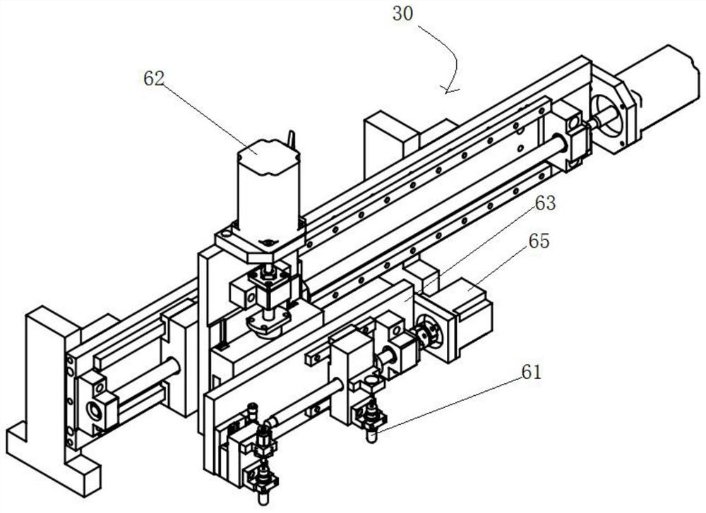
[0024] Such as figure 1 , figure 2 as shown, figure 1 It is the first three-dimensional schematic diagram of the automatic die-cutting mechanism of the present invention; figure 2 It is a connection diagram of the first pressing roller, the second pressing roller, the first driving roller and the second ...


PUM


Abstract

The invention discloses an automatic die cutting mechanism. The automatic die cutting mechanism comprises a rack, a die cutting assembly arranged on the rack, a first motor arranged on the rack and asecond motor connected with a first adjusting assembly. The first adjusting assembly is used for adjusting the distance between a second transmission roller and a first driving roller. The automatic die cutting mechanism has the following advantages that: firstly, the distance between the second transmission roller and the first driving roller can be adjusted, and in other words, the moving distance of a printed material reaching the preset die cutting position is temporarily adjusted, the speed adjusting effect is achieved, the operation manner is simple and convenient, and regulation and control are accurate; secondly, the attaching firmness of the printed material and the first driving roller is improved; and thirdly, a die does not need to be used, and for the printed material, throughthe three-axis linkage function of the die cutting assembly matched with the first driving roller, any pattern cutting can be achieved, and for die cutting of small-batch products, the advantages ofbeing low in cost and high in efficiency are achieved.

Description

technical field [0001] The invention belongs to the technical field of die-cutting equipment, and in particular relates to an automatic die-cutting mechanism. Background technique [0002] At present, die-cutting equipment is mostly used in the die-cutting process of substrates. When the die-cutting equipment is working, it needs to use molds to die-cut a large number of products. Different patterns need to use different molds, so there are cumbersome die-cutting steps and high costs. ; and most die-cutting equipment is relatively cumbersome in adjusting the transmission speed of the substrate, and lacks precision, which greatly affects the quality of die-cutting. Contents of the invention [0003] The main purpose of the present invention is to propose an automatic die-cutting mechanism to solve the technical problems mentioned in the background art. [0004] An automatic die-cutting mechanism of the present invention comprises a frame, a die-cutting assembly arranged on...

Claims


Application Information

Patent Timeline
Patent Type & Authority Applications(China)
IPC IPC(8): B26F1/38B26D7/06
CPCB26D7/0625B26F1/38
Inventor 李新侯飞
Owner BROTECH GRAPHIC
Learn More