Machining center lead screw protective cover

A machining center and protective cover technology, which is applied in the field of machining center screw protective cover, can solve the problems of metal debris flying up, screw damage, etc., and achieve the effect of preventing flying into the screw rod

Inactive Publication Date: 2021-02-26
苏州凯乔精工箱柜有限公司
View PDF0 Cites 0 Cited by
  • Summary
  • Abstract
  • Description
  • Claims
  • Application Information

AI Technical Summary

Problems solved by technology

[0002] The processing head of the machining center is mostly driven by a screw rod. Because the metal debris flies up when the processing head processes the workpiece, once these metal debris fly into the screw rod, it is easy to cause damage to the screw rod.

Method used


Image

  • Machining center lead screw protective cover
  • Machining center lead screw protective cover
  • Machining center lead screw protective cover

Examples


Embodiment

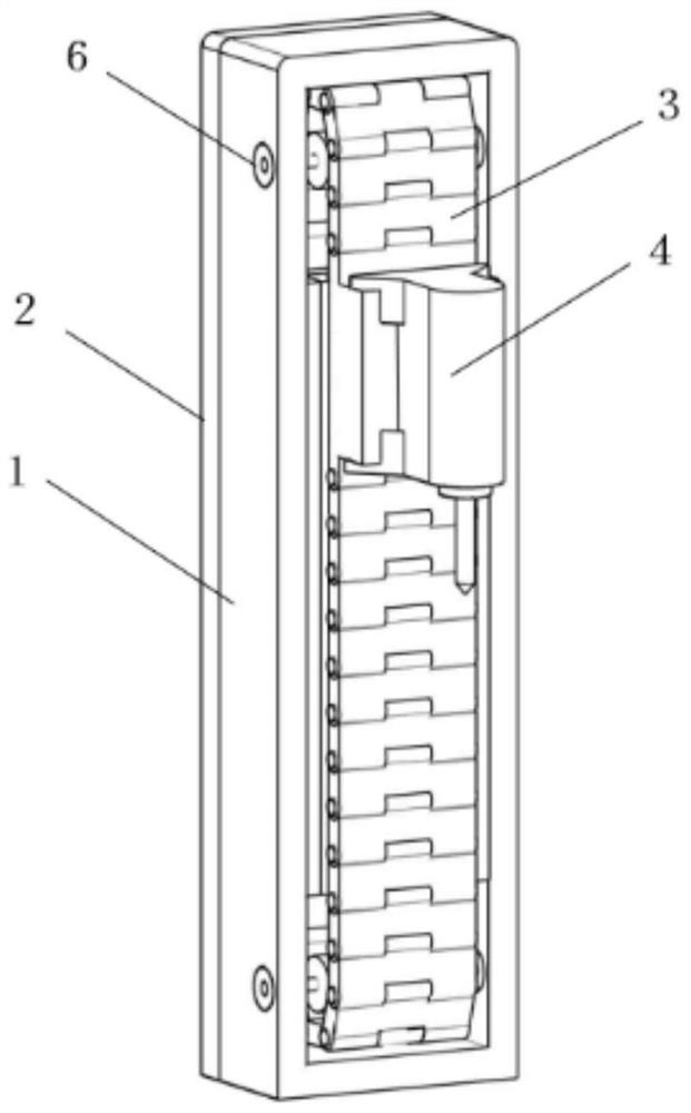
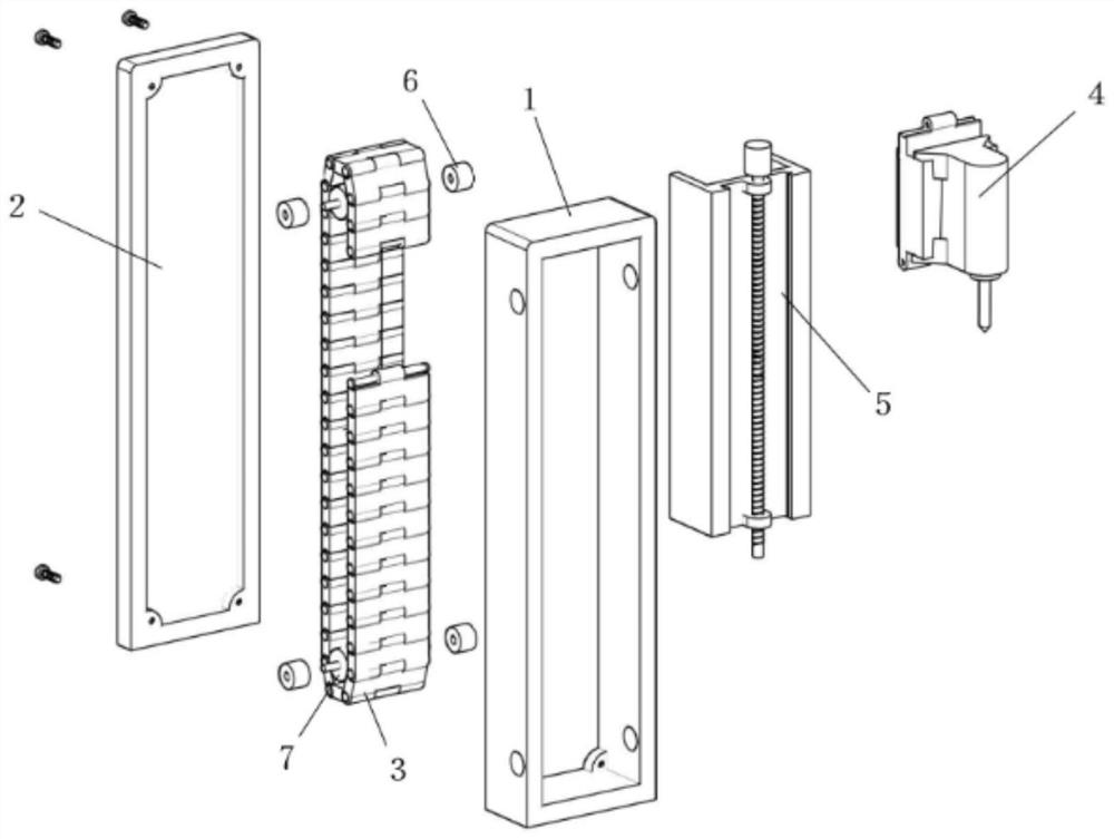
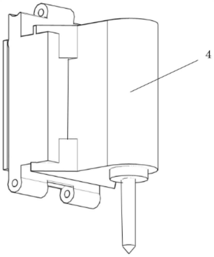
[0016] The screw protective cover of the machining center includes a screw slide rail 5, a processing head 4, and the processing head 4 slides on the screw slide rail 5, and also includes a protection chain plate 3; the protection chain plate 3 consists of several The chain blocks are hinged to each other, the front and rear ends of the base of the processing head 4 are provided with chain links that can be hinged with the chain blocks of the protection chain plate 3; the chain blocks of the protection chain plate 3 are connected to the processing head. 4. The chain links at the front and rear ends of the base are hinged together to form a closed annular chain block ring; the screw slide rail 5 is located inside the chain block ring.

[0017] The screw protective cover of the machining center also includes a fixed frame 1 and a chain shaft 7; the screw slide rail 5, the processing head 4 and the protective chain plate 3 are embedded in the fixed frame 1, and there are two chain...


PUM


Abstract

The invention discloses a machining center lead screw protective cover. The machining center lead screw protective cover comprises a lead screw sliding rail, a machining machine head and a protectivechain plate, wherein the machining machine head slides on the lead screw sliding rail; the protective chain plate is formed by hinging a plurality of chain blocks; chain links capable of being hingedto the chain blocks of the protective chain plate are arranged at the front end and the rear end of a base of the machining machine head; the plurality of chain blocks of the protective chain plate and the chain links at the front end and the rear end of the base of the machining machine head are jointly hinged to form a closed annular chain block ring; and the lead screw sliding rail is located in the chain block ring. According to the machining center lead screw protective cover, linkage of the machining machine head during movement can be achieved, and metal chippings are prevented from flying into a lead screw.

Description

technical field [0001] The invention relates to a protective cover for a screw rod of a machining center. Background technique [0002] The processing head of the machining center is mostly driven by a screw rod. When the processing head processes the workpiece, there are metal chips flying up gradually. Once these metal chips fly into the screw rod, it will easily cause damage to the screw rod. SUMMARY OF THE INVENTION [0003] The purpose of the present invention is to provide a protective cover for the screw rod of a machining center, which can realize the linkage of the machining head when moving, and prevent metal chips from flying into the inside of the screw rod. [0004] In order to achieve the above purpose, the technical solution of the present invention is to design a protective cover for the lead screw of the machining center, including a lead screw slide rail and a processing head, and the processing head slides on the screw slide rail, and also includes a pro...

Claims


Application Information

Patent Timeline
Patent Type & Authority Applications(China)
IPC IPC(8): B23Q5/40B23Q11/08
CPCB23Q5/40B23Q11/08
Inventor 季广越
Owner 苏州凯乔精工箱柜有限公司
Why Eureka
Try Eureka