Clinical treatment device for neurology department

A technology for clinical treatment and neurology, applied in the field of clinical treatment devices in neurology, can solve the problems of inconvenient liquid collection, inability to accurately control the depth of insertion into a patient, etc., and achieve the effects of convenient liquid collection, avoidance of manual puncture, and convenient operation.

Inactive Publication Date: 2021-02-26
刘瑞光
View PDF0 Cites 1 Cited by
  • Summary
  • Abstract
  • Description
  • Claims
  • Application Information

AI Technical Summary

Problems solved by technology

[0004] The purpose of the present invention is to solve the shortcomings of the existing puncture methods that mostly use hand-held puncture needles to be directly inserted into the patient's body, the depth of insertion into the patient's body cannot be accurately controlled, and the liquid is inconvenient, and a clinical treatment device for neurology is proposed.

Method used


Image

  • Clinical treatment device for neurology department
  • Clinical treatment device for neurology department
  • Clinical treatment device for neurology department

Examples


Embodiment 1

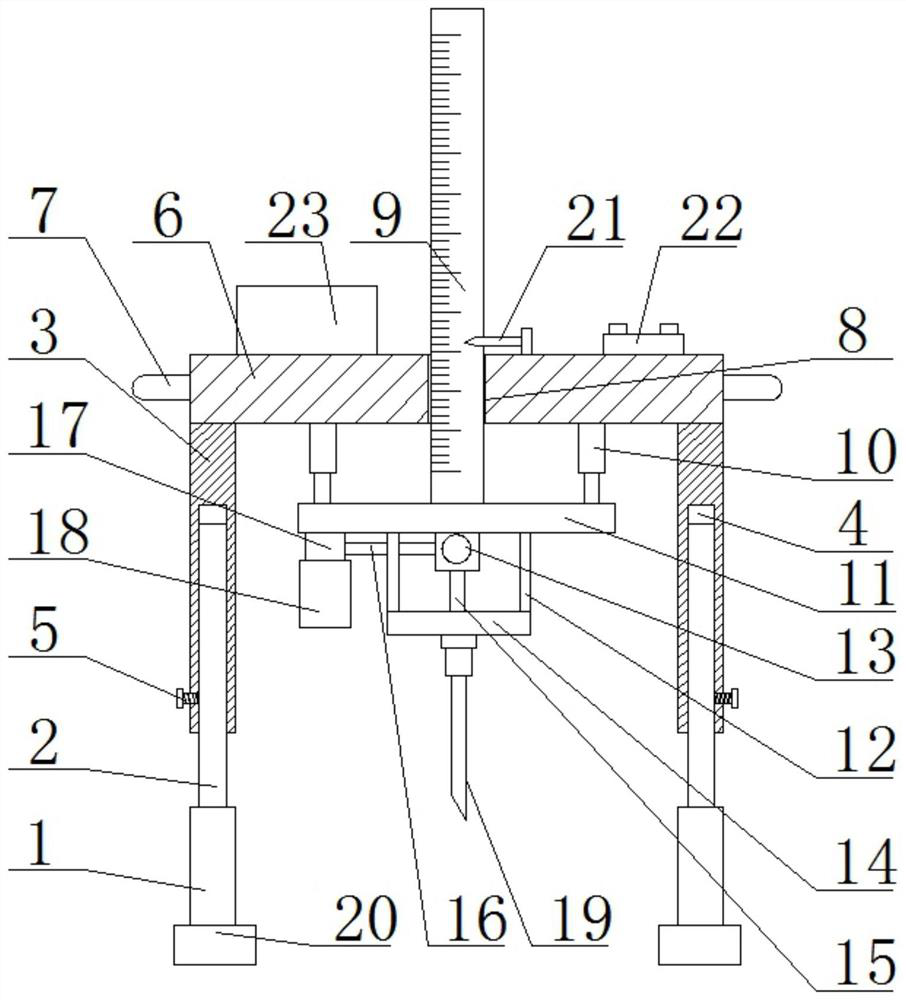
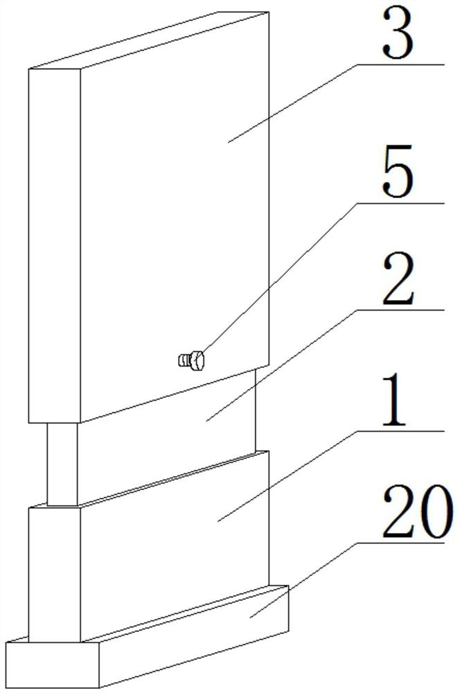
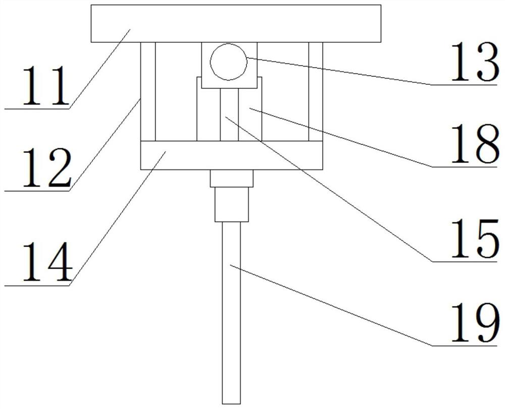
[0022] refer to Figure 1-3 , a neurology clinical treatment device, comprising two straight boards 1, the bottoms of the two straight boards 1 are fixedly installed with foot pads 20, the tops of the two straight boards 1 are fixedly installed with a board 2, and the two boards 2 Sliding boards 3 are installed on the outer sides, and the tops of the two sleeves 3 are connected to the same connecting plate 6. A sliding hole 8 is provided at the center of the top of the connecting plate 6, and a scale 9 is vertically slid in the sliding hole 8. The bottom end fixture of scale 9 is equipped with lifting plate 11, and the bottom of connecting plate 6 is fixedly connected with two telescopic motors 10, and the output shafts of two telescopic motors 10 are all fixedly connected with the top of lifting plate 11, and the top of lifting plate 11 The bottom is fixedly connected with four support rods 12, and the bottom of the four support rods 12 is fixedly connected with the same disc...

Embodiment 2

[0028] refer to Figure 1-3 , a neurology clinical treatment device, comprising two straight boards 1, the bottoms of the two straight boards 1 are fixedly installed with ground pads 20 by welding, the tops of the two straight boards 1 are fixedly installed with inserting boards 2 by welding, two The outer side of the inserting plate 2 is slidingly installed with the cover plate 3, and the tops of the two cover plates 3 are connected with the same connecting plate 6 through the rotation of the pivot pin. The top center of the connecting plate 6 is provided with a sliding hole 8, and the vertical The scale 9 is slidingly installed, and the bottom fixing part of the scale 9 is equipped with a lifting plate 11. The bottom of the connecting plate 6 is fixedly connected with two telescopic motors 10 by screws, and the output shafts of the two telescopic motors 10 are connected to the lifting plate 11. The top of the lifting plate 11 is fixedly connected by screws, the bottom of the...


PUM


Abstract

The invention belongs to the technical field of medical equipment, particularly relates to a clinical treatment device for the neurology department, and aims to solve the problems that according to anexisting puncture mode, a puncture needle is hand-held to be directly inserted into the body of a patient, the depth of the needle inserted into the body of the patient cannot be accurately controlled and liquid is inconvenient to take. The following scheme is provided currently, the clinical treatment device comprises two straight plates, wherein foot pads are fixedly installed at the bottoms ofthe two straight plates, inserting plates are fixedly installed at the tops of the two straight plates, sleeve plates are installed on the outer sides of the two inserting plates in a sleeving manner, the tops of the two sleeve plates are rotationally connected with the same connecting plate, a sliding hole is formed in the center of the top of the connecting plate, a graduated scale is installedin the sliding hole in a vertical sliding manner, a lifting plate is installed on a bottom end fixing piece of the graduated scale, and two telescopic motors are fixedly connected to the bottom of the connecting plate. The clinical treatment device is convenient to operate, avoids manual puncture of medical staff, can accurately control the depth of the needle inserted into the body of the patient, and facilitates liquid taking.

Description

technical field [0001] The invention relates to the technical field of medical equipment, in particular to a neurology clinical treatment device. Background technique [0002] Department of Neurology mainly diagnoses and treats cerebrovascular diseases, migraine, brain inflammatory diseases, myelitis, epilepsy, dementia, nervous system degenerative diseases, metabolic diseases and genetic diseases, trigeminal neuralgia, sciatic nerve disease, peripheral neuropathy and myasthenia gravis, etc. Puncture is commonly used in neurology treatment, and puncture is to insert a puncture needle into a body cavity to extract secretions for testing. [0003] Most of the existing puncture methods use hand-held puncture needles to be directly inserted into the patient's body, which cannot accurately control the depth of insertion into the patient's body, and it is inconvenient to take fluid. Contents of the invention [0004] The purpose of the present invention is to solve the shortcom...

Claims


Application Information

Patent Timeline
IPC IPC(8): A61B10/00A61B17/34
CPCA61B10/00A61B10/0045A61B17/3494
Inventor 刘瑞光赵立华王婷
Owner 刘瑞光
Why Eureka
Try Eureka