A kind of processing equipment for semiconductor light-emitting element
A technology of light-emitting components and processing equipment, which is applied in the direction of semiconductor devices, electrical components, circuits, etc., can solve the problems of inconvenient workpiece turnover, and achieve the effects of ensuring smoothness, reducing instantaneous impact force, and stabilizing mobile clamping
- Summary
- Abstract
- Description
- Claims
- Application Information
AI Technical Summary
Problems solved by technology
Method used
Image
Examples
Embodiment 1
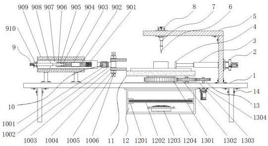
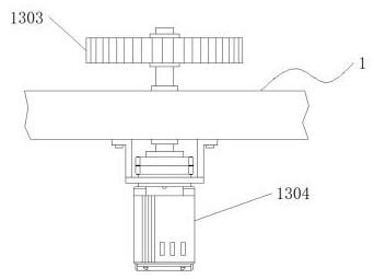
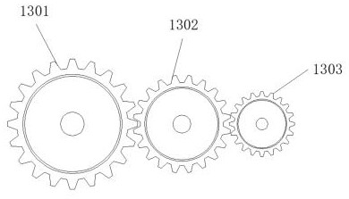
[0035] Example 1: See Figure 1-6, a kind of processing equipment for semiconductor light-emitting element, comprises workbench 1 and support foot 14, and the four corners of workbench 1 bottom are provided with support foot 14, and the top of workbench 1 is provided with processing table 11, and the bottom of workbench 11 A rotating mechanism 13 is provided between the end and the workbench 1, a clamping turning mechanism 10 is provided on one side of the processing table 11, a moving mechanism 9 is provided on one side of the top end of the workbench 1, and a chip suction mechanism is provided at the bottom end of the workbench 1. Mechanism 12, the other side of the top of the workbench 1 is provided with a pushing mechanism;
[0036] see Figure 1-6 , a processing equipment for semiconductor light-emitting elements also includes a push mechanism, the push mechanism includes a fixed frame 5, the fixed frame 5 is fixedly connected to the other side of the top of the workbenc...
Embodiment 2
[0039] Embodiment 2: The moving mechanism 9 consists of a spring 901, a first slider 902, a chute 903, a second slider 904, a hollow groove 905, a second hydraulic rod 906, a moving plate 907, a moving groove 908, a fixed seat 909 and a first Two hydraulic cylinders 910 are formed, and the fixed seat 909 is fixedly connected to one side of the top of the workbench 1. The top and bottom ends of the fixed seat 909 are provided with moving grooves 908, and a moving plate 907 is embedded between the moving grooves 908 and is connected with the moving plate 907. Flexible connection, the inside of the moving plate 907 is provided with a hollow groove 905, the top and the bottom of the hollow groove 905 are provided with chute 903, one side between the chute 903 is embedded with a second slider 904, between the chute 903 The other side of the first slider 902 is embedded, a spring 901 is provided between the first slider 902 and the inner wall of the hollow groove 905, the second hydr...
Embodiment 3
[0042] Embodiment 3: The clamping turning mechanism 10 is made up of driving motor 1001, rotating shaft 1002, splint 1003, fixed rod 1004, second cylinder 1005 and second telescopic rod 1006, and driving motor 1001 is arranged on the side of processing table 11, drives The model of the motor 1001 can be Y90S-2, the output end of the driving motor 1001 is fixedly connected with the rotating shaft 1002 through a shaft coupling, the other side of the rotating shaft 1002 is movably connected with a fixed rod 1004, and the external movable sleeve of the fixed rod 1004 has a Two sets of splints 1003, the top and the bottom of the fixed rod 1004 are fixedly connected with the second cylinder 1005, the model of the second cylinder 1005 can be MHZ2-16D / 20D, the output end of the second cylinder 1005 is provided with a second telescopic rod 1006, The second telescopic rod 1006 is fixedly connected with the splint 1003 respectively;
[0043] One side of the drive motor 1001 is fixedly co...
PUM
 Abstract
Description
Claims
Application Information
 - Generate Ideas
- Intellectual Property
- Life Sciences
- Materials
- Tech Scout
- Unparalleled Data Quality
- Higher Quality Content
- 60% Fewer Hallucinations
Browse by: Latest US Patents, China's latest patents, Technical Efficacy Thesaurus, Application Domain, Technology Topic, Popular Technical Reports.
© 2025 PatSnap. All rights reserved.Legal|Privacy policy|Modern Slavery Act Transparency Statement|Sitemap|About US| Contact US: help@patsnap.com


