Wear-resistant anti-deformation building formwork

A construction template and anti-deformation technology, which is applied in the direction of construction, building structure, formwork/formwork components, etc., can solve the problems of uneven application, deformation, and affecting the quality of concrete, so as to increase the direction of reinforcement and improve the fixed anti-deformation Effect

Inactive Publication Date: 2021-02-19
江西星铝科技有限公司
View PDF7 Cites 2 Cited by
  • Summary
  • Abstract
  • Description
  • Claims
  • Application Information

AI Technical Summary

Problems solved by technology

[0003] Most of the existing building templates are assembled into molds and then fixed with supporting structures, so when the concrete is poured into the formwork, the joint between the building formwork and the building formwork is easily subjected to a greater force load, which causes deformation and affects the strength of the concrete. The quality of the construction, and most of the existing building templates need to apply a release agent on the side that is in contact with the concrete to prevent it from sticking to the concrete during disassembly. However, most of the existing release agents are applied manually, and the application is uneven. During the period from the application of the release agent to the injection of the concrete, the release agent tends to accumulate downward under the action of gravity, which affects the quality of the concrete and reduces the wear resistance of the building formwork

Method used


Image

  • Wear-resistant anti-deformation building formwork
  • Wear-resistant anti-deformation building formwork
  • Wear-resistant anti-deformation building formwork

Examples


Embodiment Construction

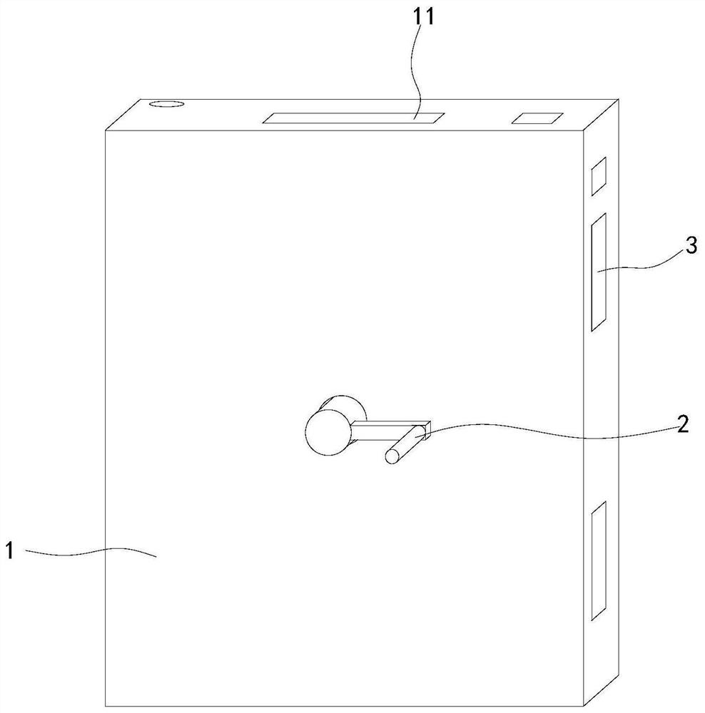
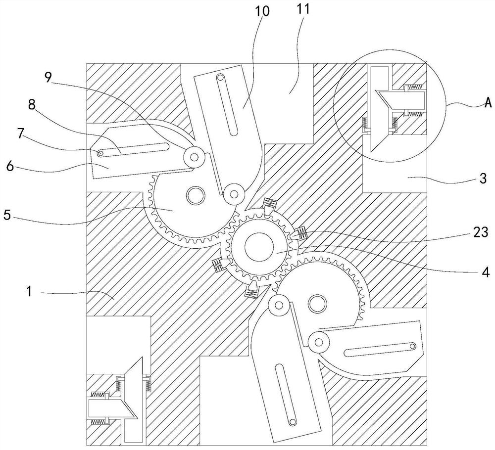
[0029] see Figures 1 to 8 , a schematic diagram of a planar structure and a schematic diagram of a three-dimensional structure of a wear-resistant and anti-deformation building formwork.

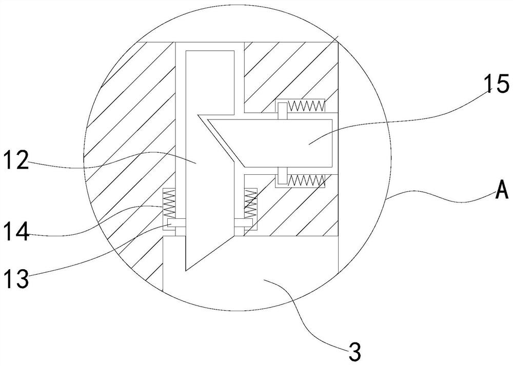
[0030] A wear-resistant and anti-deformation building formwork, comprising a device main body 1, a release agent cavity 17, a rotating handle 2 is movably installed in the center of the front of the device main body 1, a transmission gear 4 is fixedly installed in the center of the device main body 1, and the interior of the device main body 1 is relatively driven. The outer side of the gear 4 is fixedly equipped with a runner 5, the left and right sides of the device main body 1 are provided with a first card slot 3, the inside of the release agent chamber 17 is movable and installed with a trigger block 16, and the upper and lower ends of the device main body 1 are provided with a second card slot 11.

[0031] In a specific implementation, the outer side of the runner 5 is provided with ...


PUM


Abstract

The invention relates to the field of building formworks, in particular to a wear-resistant anti-deformation building formwork. The building formwork comprises a device body and a release agent cavity; a rotating handle is movably installed in the center of the front face of the device body; a transmission gear is fixedly installed in the center in the device body; a rotating wheel is fixedly installed on the outer side, opposite to the transmission gear, in the device body; and gear teeth meshed with the transmission gear are arranged on the outer side of the rotating wheel. When the rotatinghandle is manually rotated, a rotating wheel can be driven to rotate through the transmission gear, so that a first clamping plate on the edge of the upper end of the rotating wheel moves leftwards to the outer part of the device body through a rotating shaft and enters a first clamping groove of an adjacent building formwork device body; and meanwhile, a limiting rod is embedded into a limitinggroove, so that the outward moving direction of the first clamping plate can be limited, the outward moving distance of the first clamping plate is increased, and the fixing and anti-deformation effects are improved.

Description

technical field [0001] The invention relates to the field of building templates, in particular to a wear-resistant and deformation-resistant building template. Background technique [0002] The building formwork is a temporary support structure, which is manufactured according to the design requirements, so that the concrete structure and components are formed according to the specified position and geometric size, maintain their correct position, and bear the self-weight of the building formwork and the external load acting on it. The purpose of formwork engineering is to ensure the quality of concrete engineering and construction safety, speed up the construction progress and reduce engineering costs. [0003] Most of the existing building templates are assembled into molds and then fixed with supporting structures, so when the concrete is poured into the formwork, the joint between the building formwork and the building formwork is easily subjected to a greater force load...

Claims


Application Information

Patent Timeline
Patent Type & Authority Applications(China)
IPC IPC(8): E04G9/10E04G17/00E04G19/00
CPCE04G9/10E04G17/00E04G19/00
Inventor 王贞宝宋志剑段祥战国
Owner 江西星铝科技有限公司
Why Eureka
Try Eureka