A kind of prefabricated building and design method thereof
A prefabricated and architectural technology, applied in the direction of buildings, building components, building structures, etc., can solve problems such as earthquake resistance and wind resistance
- Summary
- Abstract
- Description
- Claims
- Application Information
AI Technical Summary
Problems solved by technology
Method used
Image
Examples
Embodiment 1
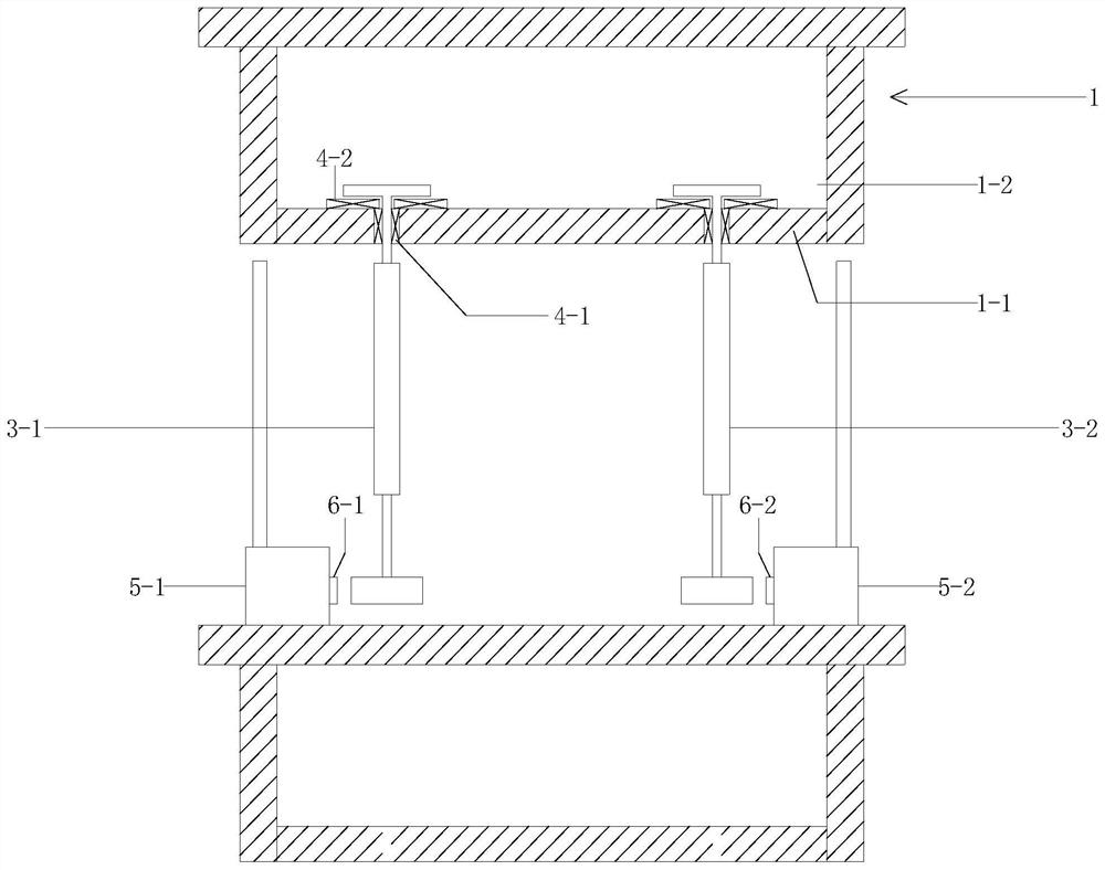
[0078] A quick assembly wall structure, which is arranged between the upper box girder 1 (belonging to the necessary technical features) and the lower box girder 2 (the lower box girder 2 can also adopt other structural forms);
[0079] It includes: a first rotating assembly 3-1, a second rotating assembly 3-2 (which is a necessary technical feature), a first base block 7-1, a second base block 7-2, and a box;
[0080] Arranged in order from left to right: the first base block 7-1, the first rotating assembly 3-1, the second rotating assembly 3-2, and the second base block 7-2;
[0081] Wherein, the box includes: a first side wall 5-1, a second side wall 5-2, and a viscous damping fluid inside the box; the first side wall 5-1, the second side wall of the wall 5-2 are parallel to each other and extend along the length direction of the beam;
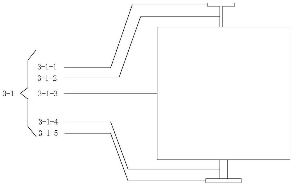
[0082] Wherein, the first rotating assembly 3-1 includes: an upper limiting plate 3-1-1, an upper connecting rod 3-1-2, a rotating plate...
Embodiment 2
[0100] Embodiment two, such as Figure 4-5 As shown, the advantage of embodiment two is to break this technical prejudice: the central axis of the lower gear 3-1-5 is on the same axis as the central axis of the rotating plate body 3-1-3;
[0101] The way of embodiment two is:
[0102] The rotating plate bodies of the first rotating assembly 3-1 and the second rotating assembly 3-2 are folded line plates, which include: the first folding plate body, the middle plate body, the second folding plate body, the first rotating assembly 3-1 The first flap body and the second flap body of the second rotating assembly 3-1 face the first side wall; the first flap body and the second flap body of the second rotating assembly 3-1 face the second side wall;
[0103] The upper connecting rod 3-1-2 is fixedly connected to the upper connecting plate, the lower connecting rod 3-1-4 is fixedly connected to the lower connecting plate, the top of the rotating plate body is fixedly connected to the ...
Embodiment 3
[0117] Embodiment 3, the solution of Embodiment 1 is to adjust the steering angle of the main body of the rotating plate through gears. That is, the steering angle-displacement is proportional.
[0118] The method of Embodiment 3 is to further meet the design requirements, that is, to meet: any S-β curve; S represents: the relative displacement between the upper box girder and the lower box girder, and β represents the displacement of the main body of the rotating plate under the displacement S turn angle.
[0119] For this requirement, make the following improvements:
[0120] The lower connecting rod 3-1-4 and the gear 3-1-5 are no longer necessary; the racks of the first base block and the second base block are also no longer necessary.
[0121] The lower end connecting rod 3-1-7 is arranged at the bottom front end and the rear end of the rotating plate body; Both sides of the connecting rod 3-1-2; and, the connecting line of the lower connecting rod 3-1-7 at the two end...
PUM
 Abstract
Description
Claims
Application Information
 - R&D Engineer
- R&D Manager
- IP Professional
- Industry Leading Data Capabilities
- Powerful AI technology
- Patent DNA Extraction
Browse by: Latest US Patents, China's latest patents, Technical Efficacy Thesaurus, Application Domain, Technology Topic, Popular Technical Reports.
© 2024 PatSnap. All rights reserved.Legal|Privacy policy|Modern Slavery Act Transparency Statement|Sitemap|About US| Contact US: help@patsnap.com


