
An accurate weighing loading robot arm and loading method

A robotic arm, precise technology, applied in weighing, measuring devices, loading/unloading, etc., can solve problems such as reducing loading efficiency, and achieve the effect of improving loading efficiency

Active Publication Date: 2022-08-02
TIANDI SCI & TECH CO LTD
View PDF0 Cites 0 Cited by
  • Summary
  • Abstract
  • Description
  • Claims
  • Application Information

AI Technical Summary

Problems solved by technology

The weighing process reduces the efficiency of loading

Method used


Image

  • An accurate weighing loading robot arm and loading method
  • An accurate weighing loading robot arm and loading method
  • An accurate weighing loading robot arm and loading method

Examples


Embodiment 1

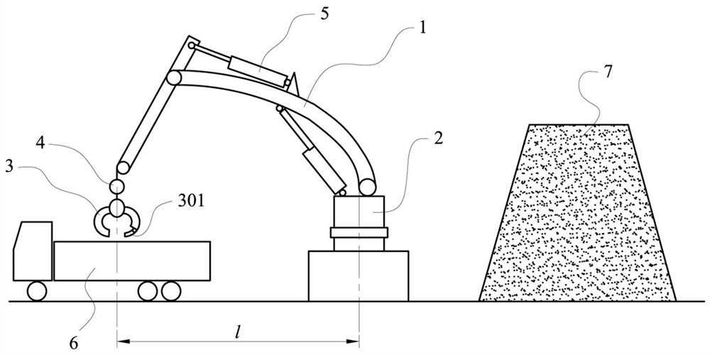
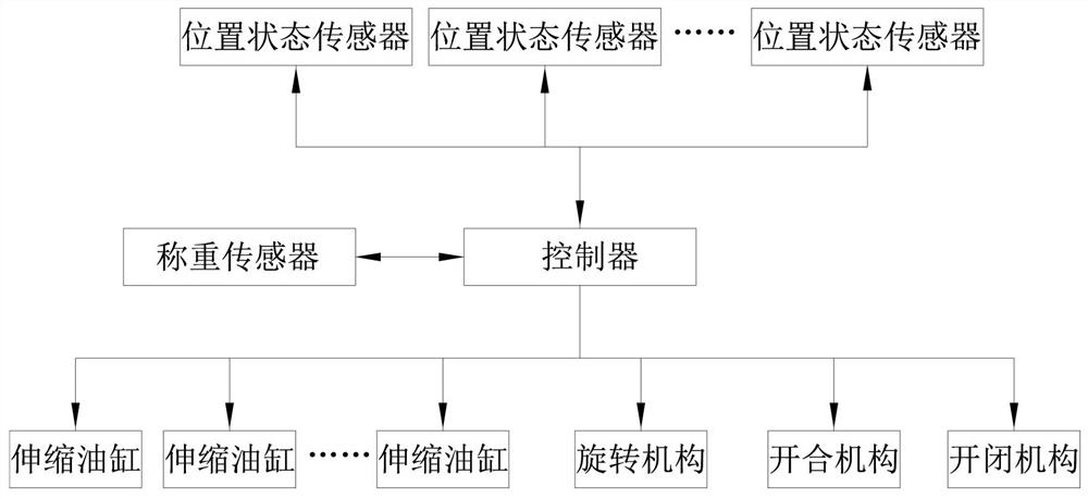
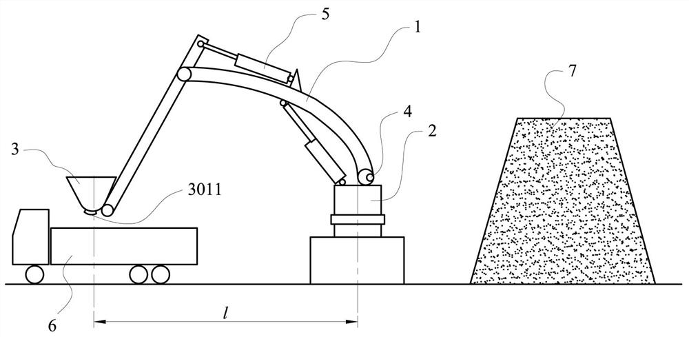
[0026] This embodiment is an accurate weighing loading robot arm, such as figure 1 , 2 shown. This embodiment includes: at least two hinged arm segments 1 ( figure 1 Shown as two arm sections in the figure), one end of the arm section is hingedly connected with the rotating platform 2 and a position state sensor is installed, and the other end of the arm section is hingedly connected with the hopper 3 and a position state sensor is installed. The load cell 4, the hopper is provided with a fine-tuning gate 301; the telescopic oil cylinder 5 of each arm segment, the rotating mechanism of the rotating platform, the opening and closing mechanism of the hopper, the opening and closing mechanism of the fine-tuning gate, as well as various position state sensors, weighing The sensor is electrically connected to the controller.

[0027] The basic principle of this embodiment is as follows: the loading manipulator is set between the material pile 6 and the transporting machine 7, an...

Embodiment 2

[0035] This embodiment is an improvement of the above-mentioned embodiment, and is a refinement of the above-mentioned embodiment about the rotating platform. The rotating platform described in this embodiment is either fixedly connected to the ground or installed on the traveling mechanism.

[0036] The rotating platform can be fixed. For example, in the application places such as ports and coal storage yards, the position of the material transportation equipment is relatively fixed. The rotating platform can be fixed on the reinforced concrete foundation with bottom corner bolts.

[0037] The running gear can be a vehicle chassis of various forms, such as a wheeled vehicle chassis with or without a track, or a tracked chassis. The vehicle chassis may be powered, such as an internal combustion engine or an electric motor, or unpowered, with motion produced by a winch or other vehicle traction.

Embodiment 3

[0039] This embodiment is an improvement of the above-mentioned embodiment, and is a refinement of the above-mentioned embodiment on the traveling mechanism. The traveling mechanism described in this embodiment is a self-powered wheeled or crawler-type traveling chassis or a non-powered wheeled trailer.

[0040] The self-powered wheeled or crawler walking chassis can be an automobile or crawler tractor driven by a motor or an internal combustion engine, and is equipped with corresponding counterweights and balance supports.


PUM


Abstract

The invention relates to an accurate weighing loading robot arm and a loading method, comprising: at least two hinged arm segments with telescopic oil cylinders and position state sensors; Sensor, the other end of the arm section is hinged to the hopper and is equipped with a position state sensor, the arm section is provided with a weighing sensor, and the hopper is provided with a fine-tuning gate; the telescopic oil cylinder of each arm section, the rotating mechanism of the rotating platform, and the opening and closing mechanism of the hopper , The opening and closing mechanism of the fine-tuning gate, as well as various position state sensors and load cells are electrically connected with the controller. The invention utilizes the sensor to cooperate with the traditional mechanical arm and the weighing sensor to realize the weighing of each obtained hopper material, and the accurate loading quantity is obtained after accumulative addition, and the realization is realized by rapidly scanning the material stack and the loading bin. It realizes the fast and accurate loading process of bulk materials, realizes the unmanned management of hopper loading, and improves the loading efficiency.

Description

technical field [0001] The present invention relates to an accurate weighing loading robot arm and a loading method, and is a transport loading mechanical device and method, and a mechanical device and method for loading and weighing bulk goods. Background technique [0002] Traditional dump trucks are often manually operated and typically load less valuable bulk materials. Because the loading process of low value basically does not carry out weighing, and only estimates the amount of loaded material through the acquisition of the hopper, it is also necessary to weigh after loading to determine the precise loading amount and replenish or unload part of the material to ensure compliance with the plan. Loading. The weighing process reduces the efficiency of loading. On the other hand, since the loading of the tipper is completely manual, the control of the telescopic, far-near opening and closing, and moving position of the robotic arm is random every time it grabs the goods...

Claims


Application Information

Patent Timeline
Patent Type & Authority Patents(China)
IPC IPC(8): B65G67/04G01G19/14G01B21/02G01B21/22G01B21/00
CPCB65G67/04G01G19/14G01B21/02G01B21/22G01B21/00
Inventor 李春雷席启明肖雅静姚树楷王伯君
Owner TIANDI SCI & TECH CO LTD
Learn More