Automatic device for wave-shifted optical fiber bending

An automatic device and bending device technology, which is applied to optical components, other household appliances, household appliances, etc., can solve the problems of affecting signal transmission, waste of wave-shifting optical fibers, and difficulty in ensuring the consistency of optical fiber bending in water baths, etc.

Pending Publication Date: 2021-02-12
INSTITUTE OF SCIENCE & TECHNOLOGY INNOVATION DONGGUAN UNIVERSITY OF TECHNOLOGY
View PDF2 Cites 1 Cited by
  • Summary
  • Abstract
  • Description
  • Claims
  • Application Information

AI Technical Summary

Problems solved by technology

[0002] China's spallation neutron source detectors include scintillator detectors. Existing scintillator detectors need to use wave-shifting optical fibers for detector signal transmission. Wave-shifting optical fibers are very expensive. Most of them are imported at present, and the price is 17 US dollars. / m, the structure of the wave-shifting fiber is brittle, and it is easy to be bent and damaged, and thus light leakage occurs, which affects signal transmission; during the development of the detector, it is necessary to realize the 90-degree bending of the wave-shifting fiber, in order to realize the 90-degree bending of the fiber Bending, designed a bracket for optical fiber bending, including a plate and a bending plate that is hinged at both ends of the plate and can only be rotated 90 degrees. There is a fiber groove on the plate and a pressing device on the bending plate. In the process of wave-shifting optical fiber water bath bending, it is difficult to control the speed, strength and time of each bending by manual bending, and the degree of each bending is different, so that the consistency of optical fiber water bath bending is difficult. Guaranteed, it is difficult to avoid accidental errors, and sometimes the optical fiber will break due to poor control of the force, resulting in the waste of expensive wave-shifting optical fiber

Method used


Image

  • Automatic device for wave-shifted optical fiber bending
  • Automatic device for wave-shifted optical fiber bending
  • Automatic device for wave-shifted optical fiber bending

Examples


Embodiment Construction

[0017] In order to enable those skilled in the art to better understand the technical solution of the present invention, the present invention will be described in detail below in conjunction with the accompanying drawings. The description in this part is only exemplary and explanatory, and should not have any limiting effect on the protection scope of the present invention. .

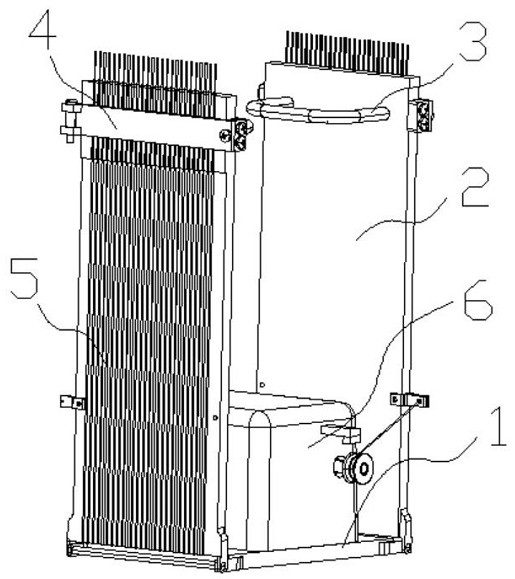
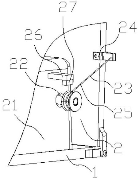
[0018] Such as Figure 1-Figure 2 As shown, the structure of the present invention is: an automatic device for bending wave-shifting optical fibers, including a flat plate 1, the two ends of the flat plate 1 are hinged with a bending plate 2 that can only rotate 90 degrees, and the flat plate 1 The first fiber groove group matched with the wave-shifting optical fiber 5 is arranged side by side, and the bending handle 3 is arranged on one side of the bending plate 2, and the pressing device 4 matched with the wave-shifting optical fiber 5 is arranged on the other side, A bending device 6 is provided on...


PUM


Abstract

The invention relates to an automatic device for wave-shifted optical fiber bending. The device comprises a flat plate, wherein two ends of the flat plate are connected with bending plates which can only rotate by 90 degrees in a hinged mode correspondingly, the flat plate is provided with a first optical fiber groove group matching a wave-shifted optical fiber side by side, one sides of the bending plates are provided with bending handles correspondingly, the other sides of the bending plates are provided with pressing devices matching the wave-shifted optical fiber correspondingly, a bendingdevice is arranged on the side, not provided with the optical fiber groove group, of the flat plate and comprises a bending driver arranged on the flat plate, bending output shafts are arranged on the front side and the rear side of the bending driver correspondingly, the two bending output shafts are symmetrical with respect to the center of a center point of the flat plate, the bending output shafts are sleeved with bending rotating cylinders, bending pull ropes are fixed to the bending rotating cylinders, and the other ends of the bending pull ropes are arranged on pull rope installation bases on the side faces of the bending plates. According to the device, the optical fiber water bath bending consistency is better, the bending efficiency is higher, the bending reject ratio is reduced, and later experimental data is more accurate and controllable.

Description

technical field [0001] The invention relates to the field of Chinese spallation neutron source detector application equipment, in particular to an automatic device for bending wave-shifting optical fibers. Background technique [0002] China's spallation neutron source detectors include scintillator detectors. Existing scintillator detectors need to use wave-shifting optical fibers for detector signal transmission. Wave-shifting optical fibers are very expensive. Most of them are imported at present, and the price is 17 US dollars. / m, the structure of the wave-shifting fiber is brittle, and it is easy to be bent and damaged, and thus light leakage occurs, which affects signal transmission; during the development of the detector, it is necessary to realize the 90-degree bending of the wave-shifting fiber, in order to realize the 90-degree bending of the fiber Bending, designed a bracket for optical fiber bending, including a plate and a bending plate that is hinged at both e...

Claims


Application Information

Patent Timeline
Patent Type & Authority Applications(China)
IPC IPC(8): B29C53/02B29L11/00
CPCB29C53/02B29L2011/0075
Inventor 魏亚东周梓荣孙志嘉唐彬吴云霞
Owner INSTITUTE OF SCIENCE & TECHNOLOGY INNOVATION DONGGUAN UNIVERSITY OF TECHNOLOGY
Why Eureka
Try Eureka