
Convenient-to-assemble auxiliary mounting rack for coating stirrer

A technology of agitator and mounting frame, which is applied in the field of auxiliary mounting frame, which can solve the problems of time-consuming and laborious assembly of the agitator and the mixing drum, affecting the normal mixing operation of the paint, and unfavorable the mixing efficiency of the paint, so as to achieve convenient disassembly and cleaning operations and quick disassembly operations , The effect of improving work efficiency

Pending Publication Date: 2021-02-12
江门市涂霸建材实业有限公司
View PDF0 Cites 0 Cited by
  • Summary
  • Abstract
  • Description
  • Claims
  • Application Information

AI Technical Summary

Problems solved by technology

[0002] The paint mixer crushes, disperses, emulsifies, and mixes the paint. Through the new high-efficiency stirring equipment with high-speed operation of the upper and lower teeth of the dispersing plate, the material is strongly sheared, impacted, crushed, and dispersed at a high speed to achieve rapid mixing, dissolution, The function of dispersing and refining is a tool commonly used in the field of home improvement today. Paint mixers often use auxiliary mounting brackets to place the motor, and the motor drives the stirring rod to achieve the stirring process of the paint inside the mixing drum. However, the existing Most of the auxiliary mounting frames of the paint mixer are fixedly connected to the mixing drum by bolts, which makes the assembly between the agitator and the mixing drum time-consuming and laborious, which affects the normal mixing operation of the paint and is not conducive to the improvement of the paint mixing efficiency. Therefore, a paint mixing Auxiliary mounting brackets for easy assembly are of great value

Method used


Image

  • Convenient-to-assemble auxiliary mounting rack for coating stirrer
  • Convenient-to-assemble auxiliary mounting rack for coating stirrer
  • Convenient-to-assemble auxiliary mounting rack for coating stirrer

Examples


Embodiment Construction

[0020] The following will clearly and completely describe the technical solutions in the embodiments of the present invention with reference to the accompanying drawings in the embodiments of the present invention. Obviously, the described embodiments are only some, not all, embodiments of the present invention. Based on the embodiments of the present invention, all other embodiments obtained by persons of ordinary skill in the art without making creative efforts belong to the protection scope of the present invention.

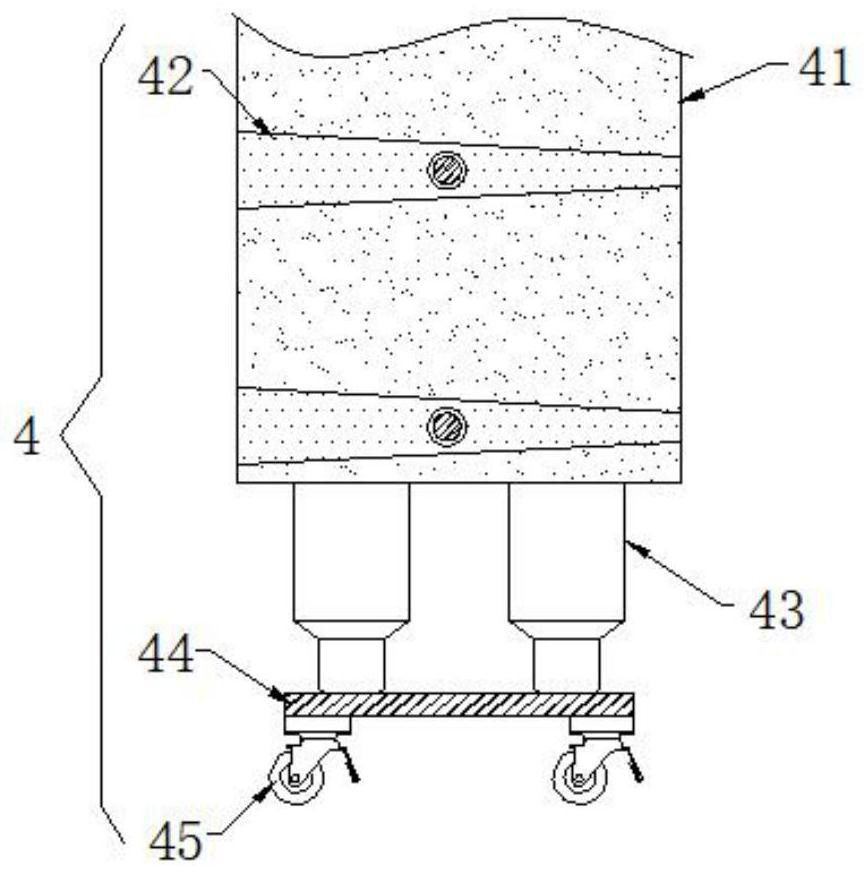
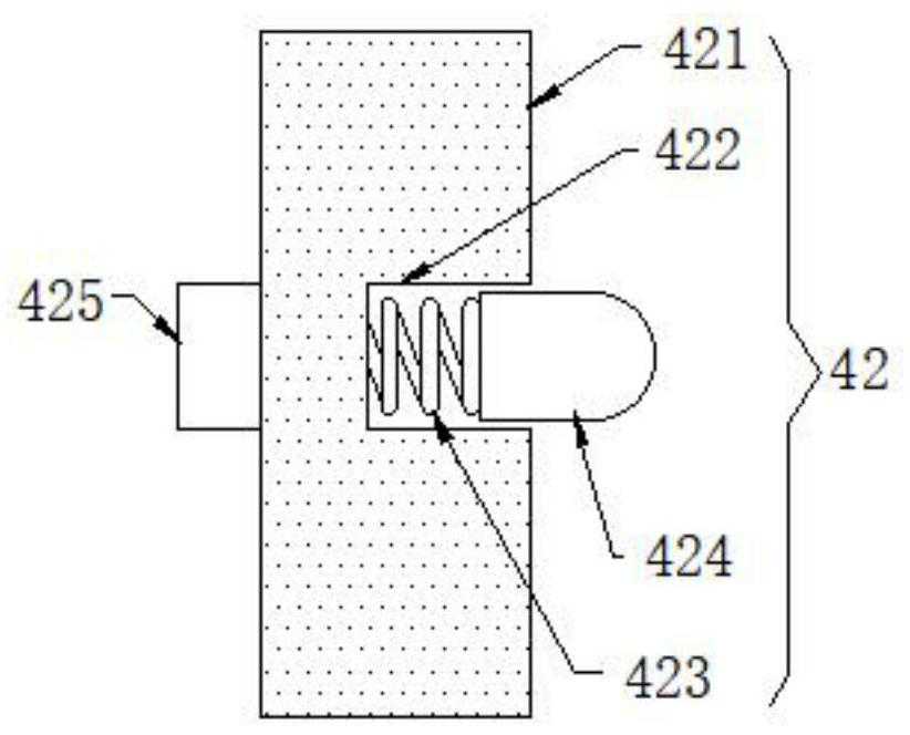
[0021] see figure 1 , the present invention provides a technical scheme of an auxiliary mounting frame for easy assembly of a paint mixer: an auxiliary mounting frame for a paint mixer that is easy to assemble, including a vertical plate 1, the top of the vertical plate 1 is fixedly connected with a horizontal plate 2, and a vertical plate 1 The bottom of the horizontal plate 2 is provided with an assembly base 4, the top of the assembly base 4 is connected wi...


PUM


Abstract

The invention discloses a convenient-to-assemble auxiliary mounting rack for a coating stirrer in the technical field of building construction equipment, which comprises a vertical plate, the top of the vertical plate is fixedly connected with a transverse plate, the bottom of the vertical plate is provided with an assembly base, the top of the assembly base is connected with a gear motor, the gear motor is connected with a screw rod, a movable plate is arranged below the transverse plate, a second mounting hole is formed in the movable plate in the longitudinal direction in a penetrating mode, and an inner cavity of the mounting hole is fixedly connected with a threaded sleeve matched with the threaded rod. An auxiliary mounting frame used by coating stirrer is convenient to assemble witha stirring cylinder so that the stirrer can rapidly stir the coating in the stirring cylinder, the stirring efficiency is improved, meanwhile, the stirrer can be conveniently detached from the stirring cylinder after stirring operation is completed, and therefore the stirring device can be conveniently detached and cleaned, and the stirrer can rapidly stir the next group of coating. Therefore, the working efficiency is improved.

Description

technical field [0001] The invention relates to the technical field of building construction equipment, in particular to an auxiliary mounting frame for a paint mixer that is easy to assemble. Background technique [0002] The paint mixer crushes, disperses, emulsifies, and mixes the paint. Through the new high-efficiency stirring equipment with high-speed operation of the upper and lower teeth of the dispersing plate, the material is strongly sheared, impacted, crushed, and dispersed at a high speed to achieve rapid mixing, dissolution, The function of dispersing and refining is a tool commonly used in the field of home improvement today. Paint mixers often use auxiliary mounting brackets to place the motor, and the motor drives the stirring rod to achieve the stirring process of the paint inside the mixing drum. However, the existing Most of the auxiliary mounting frames of the paint mixer are fixedly connected to the mixing drum by bolts, which makes the assembly between ...

Claims


Application Information

Patent Timeline
IPC IPC(8): B01F15/00B01F7/18
CPCB01F27/90B01F2035/35B01F35/43B01F2101/30
Inventor 梁传福
Owner 江门市涂霸建材实业有限公司
Learn More