
power switch circuit

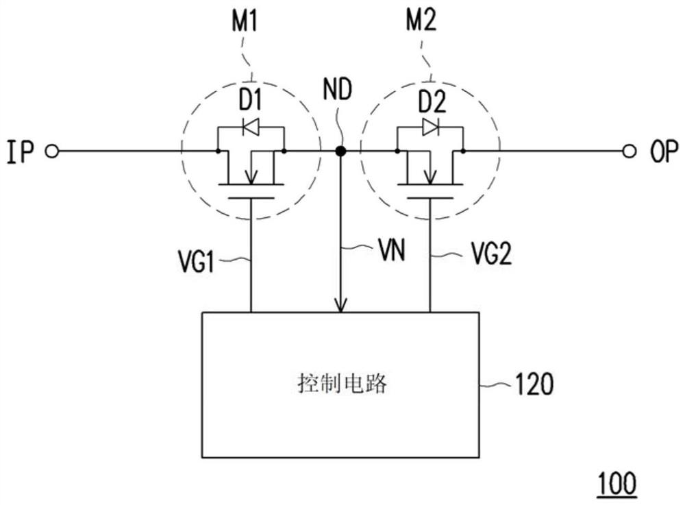
A power switch and circuit technology, applied in the direction of electronic switches, electrical components, output power conversion devices, etc., can solve the problems of uneven change of equivalent resistance value, failure of soft start, inability to switch, etc., to avoid inrush current Effect

Active Publication Date: 2022-02-25
EXCELLIANCE MOS
View PDF7 Cites 0 Cited by
  • Summary
  • Abstract
  • Description
  • Claims
  • Application Information

AI Technical Summary

Problems solved by technology

However, since the two transistors may have different threshold voltages, the two transistors may not transition from the off state to the on state simultaneously when the power switch is soft-started
If the transition time interval of one transistor from the off state to the on state overlaps only partially with the transition time interval of the other transistor from the off state to the on state, the overall equivalent resistance of the two transistors will be The change of the value is not smooth, so that the power switch will generate inrush current during the startup process and cause the soft start to fail

Method used


Image

  • power switch circuit
  • power switch circuit
  • power switch circuit

Examples


Embodiment Construction

[0055] In order to make the content of the present invention more comprehensible, the following specific embodiments are taken as examples in which the present invention can be implemented. In addition, wherever possible, elements / members / steps with the same reference numerals are used in the drawings and embodiments to represent the same or similar parts.

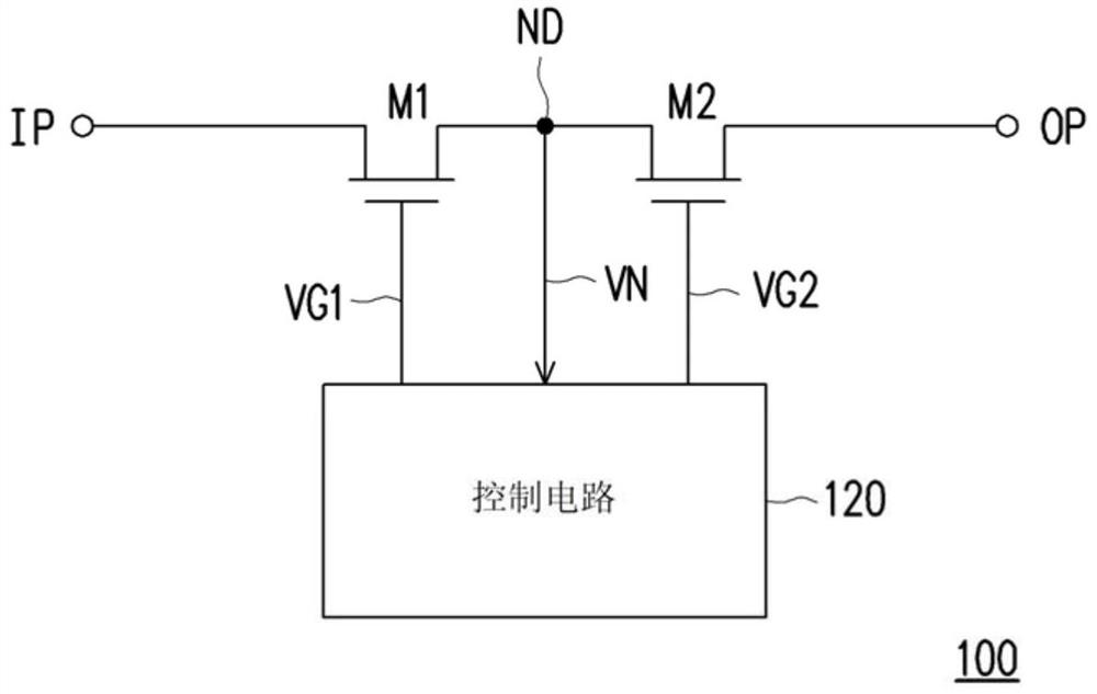
[0056] figure 1 It is a schematic circuit block diagram of a power switch circuit 100 according to an embodiment of the present invention. Please refer to figure 1 , the power switch circuit 100 may include a first transistor M1 , a second transistor M2 and a control circuit 120 . The first transistor M1 has a first terminal, a second terminal and a control terminal. The first terminal of the first transistor M1 is used as the input terminal IP of the power switch circuit 100 . The second terminal of the first transistor M1 is coupled to the node ND. The control terminal of the first transistor M1 is used for receivin...


PUM


Abstract

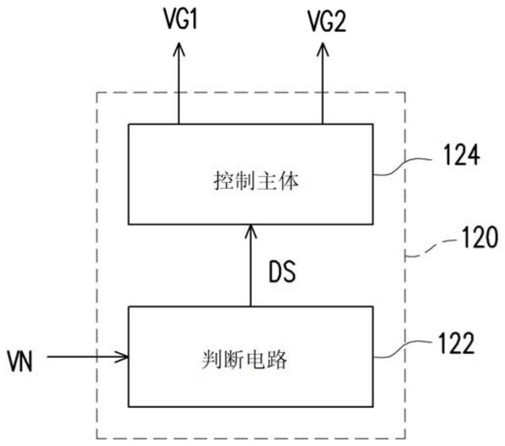
The invention provides a power switch circuit, which includes a first transistor, a second transistor and a control circuit. The first terminal of the first transistor serves as the input terminal of the power switch circuit. The second end of the first transistor is coupled to the node. The control terminal of the first transistor receives the first control voltage. The first terminal of the second transistor serves as the output terminal of the power switch circuit. The second end of the second transistor is coupled to the node. The control terminal of the second transistor receives the second control voltage. The control circuit detects the voltage of the node to determine the type of series connection between the first transistor and the second transistor, and generates a first control voltage and a second control voltage according to the type of series connection, so as to fully turn on the first transistor and the second transistor. After one of the two transistors starts to control the conduction state of the other of the first transistor and the second transistor.

Description

technical field [0001] The invention relates to a power supply circuit, in particular to a back-to-back power switch circuit capable of preventing failure of soft start. Background technique [0002] In circuit design using transistors as power switches, in order to prevent the parasitic diodes inside the transistors (i.e., body diodes) from being turned on and cause the power switches not to be completely turned off, designers usually use two transistors connected in series back-to-back To realize the power switch. However, since the two transistors may have different threshold voltages, the two transistors may not switch from the off state to the on state simultaneously when the power switch is soft-started. If the transition time interval of one transistor from the off state to the on state overlaps only partially with the transition time interval of the other transistor from the off state to the on state, the overall equivalent resistance of the two transistors will be ...

Claims


Application Information

Patent Timeline
Patent Type & Authority Patents(China)
IPC IPC(8): H02M1/36H02M1/32
CPCH02M1/36H02M1/32H02M1/0038H03K17/163H02M1/08H03K2217/0054H03K17/102H02M3/07
Inventor 李敬赞吴克伟杨珮婷
Owner EXCELLIANCE MOS
Learn More