
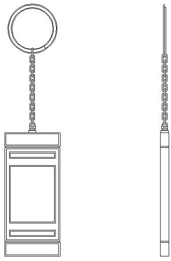
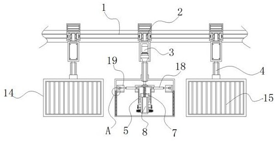
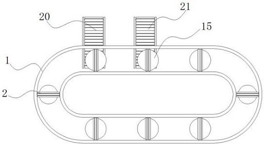
Luggage metal pendant joint detection equipment with rotating structure

A technology of rotating structure and testing equipment, applied in the direction of applying stable tension/pressure to test the strength of materials, measuring devices, instruments, etc., can solve the problems of doping to qualified pendants, missing defective products, and unable to detect pendants, etc., to achieve production Low cost, simple and reasonable structure, and the effect of avoiding the omission of defective products

Inactive Publication Date: 2021-02-09
深圳市华博自动化设计有限公司
View PDF0 Cites 0 Cited by
  • Summary
  • Abstract
  • Description
  • Claims
  • Application Information

AI Technical Summary

Problems solved by technology

[0004] Aiming at the deficiencies of the prior art, the present invention provides a detection device for the connection of metal pendants of luggage with a rotating structure, which solves the problem that the existing detection equipment in the above background technology needs to rotate for a period of time when detecting the pendants, and often can only Random inspection of the produced pendants cannot be carried out on every pendant, which will easily lead to the problem of missing defective products and mixing them into qualified pendants

Method used


Image

  • Luggage metal pendant joint detection equipment with rotating structure
  • Luggage metal pendant joint detection equipment with rotating structure
  • Luggage metal pendant joint detection equipment with rotating structure

Examples


Embodiment Construction

[0028] The following will clearly and completely describe the technical solutions in the embodiments of the present invention with reference to the accompanying drawings in the embodiments of the present invention. Obviously, the described embodiments are only some, not all, embodiments of the present invention.

[0029] In the description of the present invention, unless otherwise stated, the meaning of "plurality" is two or more; the terms "upper", "lower", "left", "right", "inner", "outer" , "front end", "rear end", "head", "tail", etc. indicate the orientation or positional relationship based on the orientation or positional relationship shown in the drawings, and are only for the convenience of describing the present invention and simplifying the description, rather than indicates or implies that the device or element referred to must have a particular orientation, be constructed and operate in a particular orientation, and therefore should not be construed as limiting the...


PUM


Abstract

The invention discloses luggage metal pendant joint detection equipment with a rotating structure, and relates to the technical field of luggage metal pendant detection, and the luggage metal pendantjoint detection equipment specifically comprises a circulating slide rail, a detection clamping mechanism and a protective cover assembly; a vertical slide frame is connected to the interior of the circulating slide rail, and an electric telescopic rod is connected to the bottom of a rotating motor; the detection clamping mechanism is fixed to the bottom end of the electric telescopic rod, the protective cover assembly is fixed to the middle section of the outer wall of the electric telescopic rod, and the first feeding belt and the second feeding belt are both filled with second adsorption magnetic powder. According to the luggage metal pendant joint detection equipment with the rotating structure, the detection clamping mechanism circularly slides above the discharging port of the assembling equipment, so that each assembled pendant is detected, defective product omission caused by a sampling inspection mode is avoided, and the equipment has the advantages of being simple and reasonable in structure and low in production cost, and can be suitable for large-scale application and popularization.

Description

technical field [0001] The invention relates to the technical field of detection of metal pendants of luggage, in particular to a detection device for the joint of metal pendants of luggage with a rotating structure. Background technique [0002] Luggage metal pendants (hereinafter referred to as pendants) are decorative pendants made of metal, generally composed of buckles, rope chains and decorative pendants. The rope chain plays a very important role in it. One end is connected to the buckle, and the other end is connected to the The connection of the decorative pendant is the connection tie between the buckle and the decorative pendant. In order to test the firmness of the connection between the rope chain and the buckle and the decorative pendant, the centrifugal force is often used to drive the whole to rotate with the buckle as the center of the circle, and connect after a certain period of time. If the connection is intact and does not fall off, it means that the con...

Claims


Application Information

Patent Timeline
Patent Type & Authority Applications(China)
IPC IPC(8): G01N3/08G01N3/02G01N19/04B07C5/38B07C5/36
CPCB07C5/362B07C5/38G01N3/02G01N3/08G01N19/04
Inventor 黄军梅黄镇鹏
Owner 深圳市华博自动化设计有限公司
Learn More