


Quick Research
Generate reliable direction feasibility study reports for your R&D in just a few steps.

Technical Q&A
Discover and master advanced knowledge NOW. Basics, ideas, possibilities, all at once.

Find Solutions
As an expert in R&D theories, this can generate solutions to your technical problems instantly.

Evaluate Feasibility
Analyze your overall solution with one click, know your potential R&D risks in advance.

Monitor Landscape
Get weekly tech updates, stay abreast of the latest tech innovations and key insights.
Axial flow pump for sewage treatment equipment
A technology for sewage treatment equipment and axial flow pumps, which is applied to axial flow pumps, mechanical equipment, components of pumping devices for elastic fluids, etc., and can solve problems such as cavitation, shortened service life, and easy damage
- Summary
- Abstract
- Description
- Claims
- Application Information
AI Technical Summary
Problems solved by technology
Method used
Image

Examples
Embodiment 1
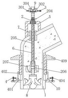
[0033] An axial flow pump for sewage treatment equipment, comprising a casing 1, a square frame 5 is fixedly connected to the top of the casing 1, and a thick rod 6 is rotatably connected to the top of the square frame 5, and the thick rod 6 is rotated through the top bearing of the square frame 5 under force , the top of the thick rod 6 is equipped with an adjustment mechanism 2, the adjustment mechanism 2 includes a curved rod 201, a cover plate 202, a notch 203, an insertion rod 204, a long rod 205, a wide plate 206 and a guide vane 207, the two curved rods 201 The inner sides are respectively plugged in with the tops of the left and right sides of the thick rod 6, and the tops of the two curved rods 201 are slidingly engaged with the bottom left and right sides of the cover plate 202 respectively, and the cover plate 202 is rotated through the top of the curved rod 201 under force, and at the same time It plays a supporting role for the sleeve plate 202, and the outer walls...
Embodiment 2
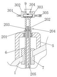
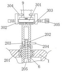
[0036] As an option, see Figure 1-3 , an axial flow pump for sewage treatment equipment, a fixing mechanism 3 is installed inside the slot plate 9, and the fixing mechanism 3 includes a double-ended stud 301, a vertical plate 302, a thin rod 303, a short rod 304 and a handle 305, and the double-ended stud The outer wall of 301 is rotatably connected with the inner wall of slot plate 9, and the double-ended stud 301 is forced to rotate through the inner wall bearing of slot plate 9. The inner sides of the vertical boards 302 are fixedly connected with the outer sides of the thin rods 303 respectively, and the thin rods 303 prevent the vertical boards 302 from rotating, and the outer walls of the two thin rods 303 are respectively inserted into the left and right sides of the front bottom of the slot plate 9. The top of the inner wall of the plate 302 is respectively affixed to the outside of the short bar 304, and the right side of the stud 301 is affixed to the left side of t...
Embodiment 3
[0039] As an option, see figure 1 , 5and 6, an axial flow pump for sewage treatment equipment, a control mechanism 4 is installed on the top of the two support plates 10, and the control mechanism 4 includes a triangular plate 401, a curved plate 402, a round rod 403, a straight plate 404, bolts 405, and a first bump 406 , the second bump 407, the vertical plate 408 and the curved block 409, the bottom of the triangular plate 401 is fixedly connected to the top right side of the support plate 10, the front of the triangular plate 401 is connected to the bottom of the curved plate 402 in rotation, and the curved plate 402 is forced to pass through The front pin shaft of the triangular plate 402 rotates, the front left side of the curved plate 402 is fixedly connected to the rear end surface of the round rod 403, the outer wall of the round rod 403 slides and engages with the groove on the right side of the straight plate 404, and the round rod 403 receives force through the str...
PUM
 Abstract
Description
Claims
Application Information
 - R&D Engineer
- R&D Manager
- IP Professional
- Industry Leading Data Capabilities
- Powerful AI technology
- Patent DNA Extraction
Browse by: Latest US Patents, China's latest patents, Technical Efficacy Thesaurus, Application Domain, Technology Topic, Popular Technical Reports.
© 2024 PatSnap. All rights reserved.Legal|Privacy policy|Modern Slavery Act Transparency Statement|Sitemap|About US| Contact US: help@patsnap.com