


Quick Research
Generate reliable direction feasibility study reports for your R&D in just a few steps.

Technical Q&A
Discover and master advanced knowledge NOW. Basics, ideas, possibilities, all at once.

Find Solutions
As an expert in R&D theories, this can generate solutions to your technical problems instantly.

Evaluate Feasibility
Analyze your overall solution with one click, know your potential R&D risks in advance.

Monitor Landscape
Get weekly tech updates, stay abreast of the latest tech innovations and key insights.
Expanding type cloth clamping mechanism and embroidery frame
An expansion and cloth clamping technology, applied in the field of embroidery machines, can solve the problems of indentation on the cloth, failure of the cloth fixation, insufficient clamping force, etc., and achieves the effect of reliable clamping and fixing, wide application range and flexible adjustment.
- Summary
- Abstract
- Description
- Claims
- Application Information
AI Technical Summary
Problems solved by technology
Method used
Image


Examples
Embodiment 1
[0038] The expandable cloth clamping mechanism of this embodiment, such as Figure 1-2 As shown, it includes a base unit 10, a cloth supporting unit 20, a cloth pressing unit 30 and a driving unit. Wherein, the cloth supporting unit 20 is arranged on the base unit 10, and the base unit is used as the border of the embroidery frame. In practical application, some embroidery frames are only clamped and fixed to the cloth at two opposite sides, and some embroidery frames are clamped and fixed to the cloth at all four frame sides. Wherein, the frame edge for clamping the cloth is composed of the expanding cloth clamping mechanism of this embodiment.
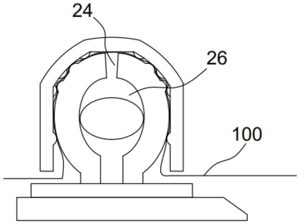
[0039] In this embodiment, the cloth supporting unit 20 includes two oppositely disposed support arms, and a drive cavity 26 is disposed between the oppositely disposed support arms. In this embodiment, the lower end of the support arm is a connecting end and is connected to the base unit, and the upper end of the support arm is a ...
Embodiment 2
[0048] The difference between the expanding cloth clamping mechanism of this embodiment and the first embodiment is that the driving unit is different from the first embodiment.
[0049] In this embodiment, the driving unit adopts a deformable filling balloon tube 50, and the deformable filling balloon tube 50 is connected with a gas or liquid filling system. It should be noted that the gas or liquid filling system is an existing technology, and its specific structure is not the invention point of this application. Conventional technical means will not be described in detail.
[0050] In this embodiment, a preferred structure of the deformable filling balloon tube 50 is as follows: Figure 4 As shown, the deformable filling tube 50 includes an outer limiting tube 52 and an inner filling tube 51, wherein the deformable filling tube 51 is filled with gas or liquid. The effect of the limit tube 52 is to control the maximum deformation of the deformed filling tube, so as to prev...
Embodiment 3
[0052] The expandable cloth clamping mechanism of this embodiment is as Figure 5 , Image 6 As shown, the difference from the second embodiment is that, firstly, one of the support arms is a fixed arm 25, and the other support arm is a movable arm 21; secondly, the configuration of the cloth pressing unit 30 is different.
[0053] In this embodiment, the cross section of the cloth pressing unit 30 is close to a square with one side open, and there is no concave-convex structure between the cloth pressing unit 30 and the cloth supporting unit 20 .
[0054] Of course, as the deformable structural form of this embodiment, firstly, the cloth pressing unit 30 can adopt the same structure as that of Embodiment 1 and Embodiment 2; Concavo-convex structure; thirdly, the drive unit can adopt the eccentric rod shown in the first embodiment.
PUM
 Abstract
Description
Claims
Application Information
 - R&D Engineer
- R&D Manager
- IP Professional
- Industry Leading Data Capabilities
- Powerful AI technology
- Patent DNA Extraction
Browse by: Latest US Patents, China's latest patents, Technical Efficacy Thesaurus, Application Domain, Technology Topic, Popular Technical Reports.
© 2024 PatSnap. All rights reserved.Legal|Privacy policy|Modern Slavery Act Transparency Statement|Sitemap|About US| Contact US: help@patsnap.com