
An integrated thermal management system for electric vehicles

A thermal management system and technology for electric vehicles, applied in the field of integrated thermal management systems for electric vehicles, can solve the problems of cabin comfort, battery safety conflicts, inability to heat batteries, and inability to independently adjust, etc. Solve the effect of difficult heating

Active Publication Date: 2022-03-08
GUANGZHOU INST OF ENERGY CONVERSION - CHINESE ACAD OF SCI
View PDF3 Cites 0 Cited by
  • Summary
  • Abstract
  • Description
  • Claims
  • Application Information

AI Technical Summary

Problems solved by technology

However, there are still some technical problems to be solved in the integrated thermal management system based on direct refrigerant cooling: First, in the traditional system, the cabin evaporator and the battery cooling plate adopt a parallel structure, and the evaporation temperature of the refrigerant in the evaporator and cooling plate It is very close and cannot be adjusted independently, which leads to a conflict between the comfort of the cabin and the safety of the battery; secondly, in the traditional system, only low-temperature refrigerant circulates in the battery cooling plate, which cannot directly heat the battery, and cannot be heated by an electric auxiliary system. The heat heats the refrigerant to indirectly heat the battery
These two technical problems limit the promotion of comprehensive thermal management systems based on direct refrigerant cooling, leading many electric vehicle manufacturers to adopt non-phase-change liquid cooling technologies with more complex structures and lower thermal management capabilities.

Method used


Image

  • An integrated thermal management system for electric vehicles
  • An integrated thermal management system for electric vehicles
  • An integrated thermal management system for electric vehicles

Examples


Embodiment 1

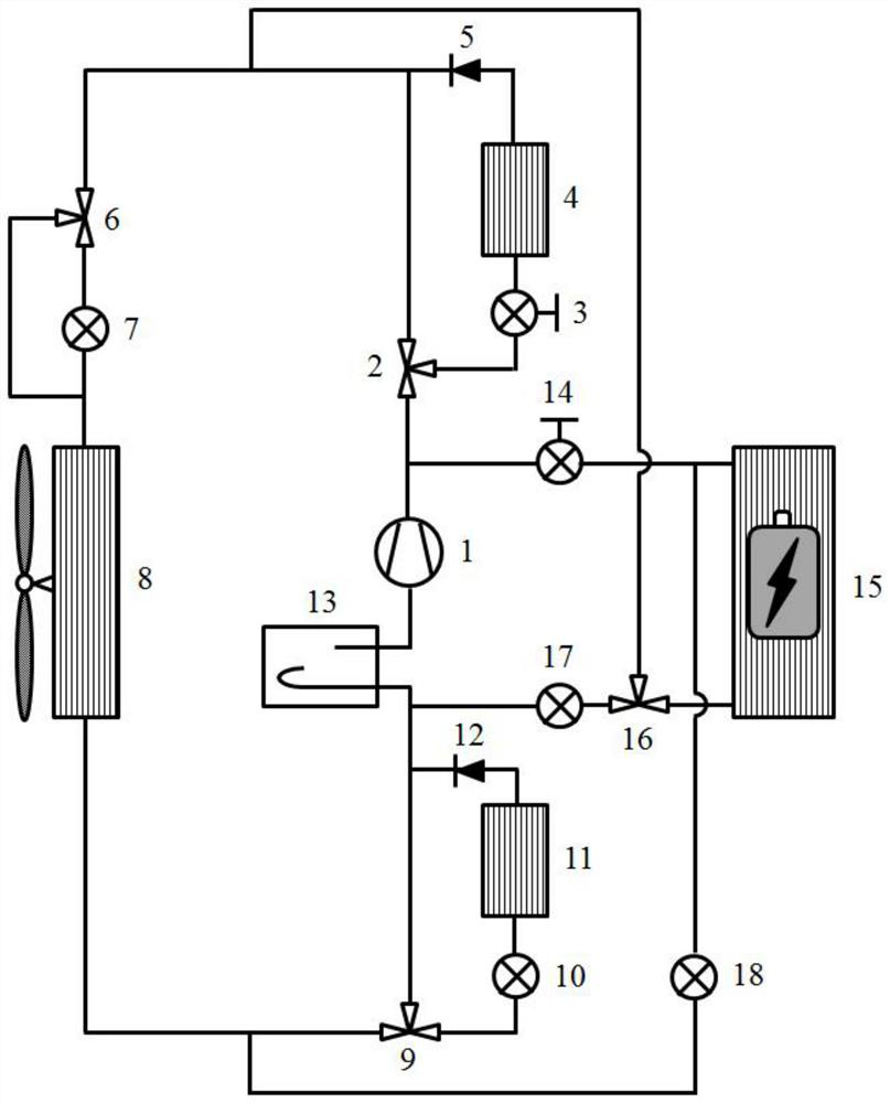
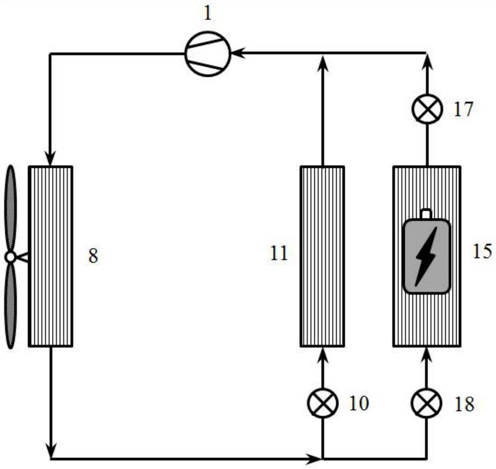
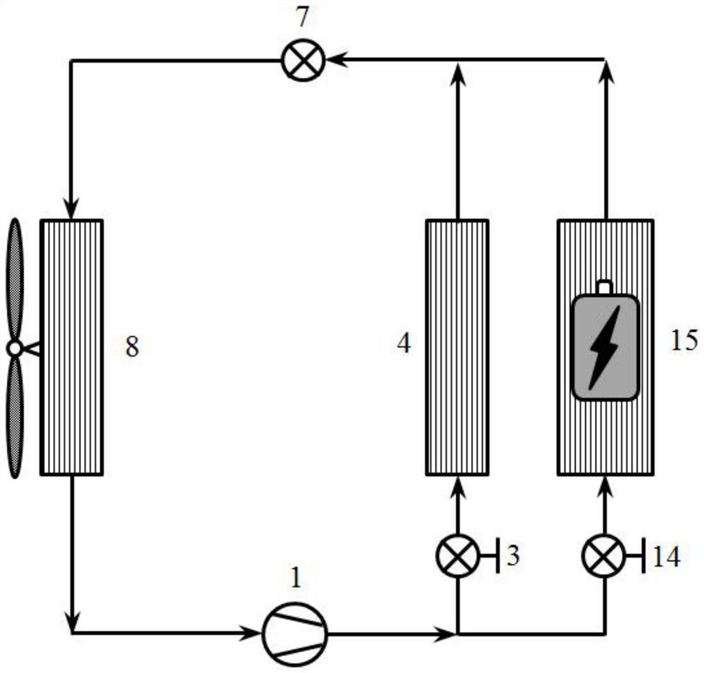
[0034] refer to figure 1 , is a comprehensive thermal management system for electric vehicles, including a compressor 1, a cabin condenser 4, a cabin evaporator 11, a front heat exchanger 8, a battery heat exchange module 15, a gas-liquid separator 13, and a first tee Valve 2, second three-way valve 6, third three-way valve 9, fourth three-way valve 16, first one-way valve 5, second one-way valve 12, first flow regulating valve 3, second flow regulating valve 14. The first electronic expansion valve 7, the second electronic expansion valve 10, the third electronic expansion valve 18, and the fourth electronic expansion valve 17; the compressor 1, the first three-way valve 2, the first flow regulating valve 3, Cabin condenser 4, first one-way valve 5, second three-way valve 6, first electronic expansion valve 7, front heat exchanger 8, third three-way valve 9, second electronic expansion valve 10, cabin evaporation The compressor 11, the second one-way valve 12, and the gas-li...


PUM


Abstract

The invention discloses a comprehensive heat management system for an electric vehicle, which includes an air-conditioning heat pump subsystem and a battery heat management subsystem; the air-conditioning heat pump subsystem is a vapor compression air-conditioning heat pump system using refrigerant as a working medium. The battery thermal management subsystem and the air-conditioning heat pump subsystem share the compressor and refrigerant working fluid. The electric vehicle comprehensive thermal management system includes a compressor, a cabin condenser, a cabin evaporator, a head heat exchanger, a battery heat exchange module, a gas-liquid separator, a first three-way device, a second three-way device, a second Three three-way device, fourth three-way device, first one-way valve, second one-way valve, first flow regulating valve, second flow regulating valve, first throttle valve, second throttle valve, third section Throttle valve, fourth throttle valve. The present invention can enable the thermal management of the electric vehicle to directly cool and heat the battery with a refrigerant without resorting to other auxiliary heating systems, and realize independent control of the cooling temperature of the cabin and the battery in the cabin cooling and battery cooling modes , while ensuring the safety of the battery, it also takes into account the comfort of the cabin air.

Description

technical field [0001] The invention relates to the technical field of electric vehicles, in particular to an electric vehicle comprehensive thermal management system. Background technique [0002] With the improvement of battery technology, electric vehicles are gradually replacing traditional fuel-powered internal combustion engine vehicles and becoming the main development direction of new energy vehicles. Electric vehicles use the electric energy stored in the power battery as the source of system power. In order to ensure the safe operation of the power battery in the optimal temperature range, it is necessary to carry out thermal management control on it. In addition, in order to ensure the comfort of the passengers and driving safety, the temperature and humidity of the air in the cabin also need to be adjusted and controlled. The battery, the thermal management system of the motor and the air conditioning system of the cabin together constitute the comprehensive the...

Claims


Application Information

Patent Timeline
Patent Type & Authority Patents(China)
IPC IPC(8): B60H1/00B60H1/32B60L58/26B60L58/27
CPCB60H1/00278B60H1/00392B60H1/00485B60H1/3204B60H1/3227B60H1/3228B60L58/26B60L58/27Y02T10/70
Inventor 郭剑蒋方明
Owner GUANGZHOU INST OF ENERGY CONVERSION - CHINESE ACAD OF SCI
Learn More