
Rapid calibration method for directional antenna angle based on celestial body tracking scanning

A directional antenna and celestial body technology, which is applied in the field of aerospace measurement and control, can solve the problems of high cost, poor mobility, and high calibration cost, and achieve the effects of improving mobility, reducing costs, and improving deployment efficiency

Active Publication Date: 2021-02-05
NO 63921 UNIT OF PLA
View PDF14 Cites 3 Cited by
  • Summary
  • Abstract
  • Description
  • Claims
  • Application Information

AI Technical Summary

Problems solved by technology

[0004] The traditional antenna angle calibration methods for tower calibration and aircraft calibration have their own shortcomings: the tower calibration method needs to build a relatively tall calibration tower at a position where the distance from the antenna satisfies the far-field condition, and the preliminary preparation The cost is high, and it is not suitable for the case where the antenna is a mobile station; for aircraft calibration, it is necessary to dispatch the aircraft or the aircraft used for calibration is within the observable range of the antenna to be calibrated, and the antenna needs to be combined with the aircraft Real-time tracking device, expensive and complicated to operate
Both of the above two antenna angle calibration methods have disadvantages such as high calibration cost, poor mobility, and long calibration time.

Method used


Image

  • Rapid calibration method for directional antenna angle based on celestial body tracking scanning
  • Rapid calibration method for directional antenna angle based on celestial body tracking scanning

Examples


Embodiment Construction

[0030] In order to more clearly describe the embodiments of the present invention or the technical solutions in the prior art, the following will briefly introduce the drawings that are used in the embodiments. Apparently, the drawings in the following description are only some embodiments of the present invention, and those skilled in the art can also obtain other drawings according to these drawings without creative efforts.

[0031] The present invention will be described in detail below in conjunction with the accompanying drawings and specific embodiments, and the embodiments cannot be repeated here one by one, but the embodiments of the present invention are not therefore limited to the following embodiments.

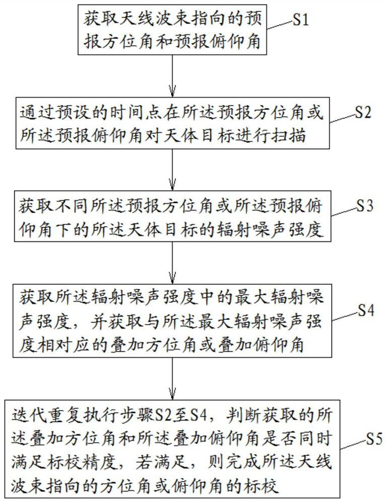
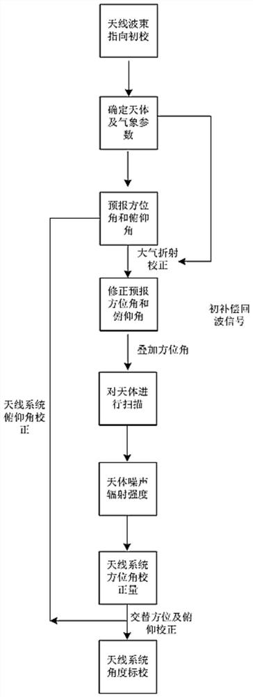
[0032] combine figure 1 and figure 2 As shown, according to an embodiment of the present invention, a method for quickly calibrating the directional antenna angle based on celestial body tracking and scanning of the present invention includes:

[0033] S0. Carr...


PUM


Abstract

The invention relates to a rapid calibration method for a directional antenna angle based on celestial body tracking scanning. The method comprises the following steps: S1, obtaining a forecast azimuth angle and a forecast pitch angle pointed by an antenna beam; S2, scanning a celestial body target at the forecast azimuth angle or the forecast pitch angle through a preset time point; S3, acquiringthe radiation noise intensity of the celestial body target under different forecast azimuth angles or forecast pitch angles; S4, acquiring the maximum radiation noise intensity in the radiation noiseintensity, and acquiring a superimposed azimuth angle or a superimposed pitch angle corresponding to the maximum radiation noise intensity; and S5, iteratively and repeatedly executing the steps S2 to S4, judging whether the obtained superposed azimuth angle and the superposed pitch angle meet calibration precision at the same time, and if so, finishing calibration of the azimuth angle or the pitch angle pointed by the antenna beam. The method is low in cost, is not liable to be affected by weather conditions, and can work all day long.

Description

technical field [0001] The invention relates to the field of aerospace measurement and control, in particular to a method for quickly calibrating the angle of a directional antenna based on celestial body tracking and scanning. Background technique [0002] Directional antennas, especially beam directional antennas, have high gain in the main beam, but narrow beam antennas are sensitive to pointing errors, and calibration of systematic errors in antenna beam pointing is required. The beam pointing of the antenna can be calculated from the results of its azimuth encoder and pitch encoder. Due to the change of antenna position, antenna reassembly error, antenna gravitational deformation, mechanical system affected by temperature and other factors, the reading of the antenna angle encoder There is a systematic difference between the actual pointing of the antenna beam and this difference changes with environmental factors. The purpose of angle calibration is to obtain this diff...

Claims


Application Information

Patent Timeline
Patent Type & Authority Applications(China)
IPC IPC(8): G01C1/00G01R29/10G01B7/30
CPCG01C1/00G01R29/10G01B7/30
Inventor 郭永强张国亭
Owner NO 63921 UNIT OF PLA
Learn More