Camera quick mounting seat

A quick-installing and camera technology, applied in the directions of cameras, camera bodies, supporting machines, etc., can solve the problems of inconvenient operation, high production cost, insufficient safety, etc., and achieve a one-way lock with a simple structure, easy production, installation, and manufacturing. low cost effect

Pending Publication Date: 2021-02-05
深圳市为荣科技有限公司
View PDF0 Cites 2 Cited by
  • Summary
  • Abstract
  • Description
  • Claims
  • Application Information

AI Technical Summary

Problems solved by technology

[0002] There are usually two connection methods between the camera and the tripod. The first connection method is to directly connect the camera and the tripod. This connection method is inconvenient to operate due to the relatively large volume of the camera and the tripod. It is easy for the equipment to fall; the second connection method is to install a mounting seat with a quick-release plate on the tripod. This type of mounting seat is usually equipped with a lock on both sides to form a two-way press lock. Press the locks on both sides to take out the quick release plate, connect the small quick release plate to the camera, and then put the quick release plate back on the mounting base. This connection method avoids the problem of the first connection method, but two-way The push lock is not convenient in operation, and the structure is relatively complicated, resulting in high production process requirements and high production costs. When installing back to the mounting seat, it needs to be installed in the corresponding direction. It is necessary to observe the corresponding direction every time. The lock on the mounting base may be accidentally pressed, causing the camera or tripod to fall, which is not safe enough

Method used


Image

  • Camera quick mounting seat
  • Camera quick mounting seat
  • Camera quick mounting seat

Examples


Embodiment Construction

[0021] The present invention will be further described below in conjunction with accompanying drawing and specific embodiment:

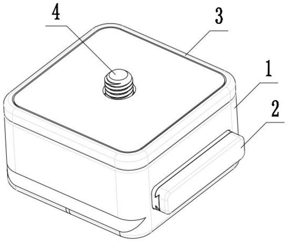
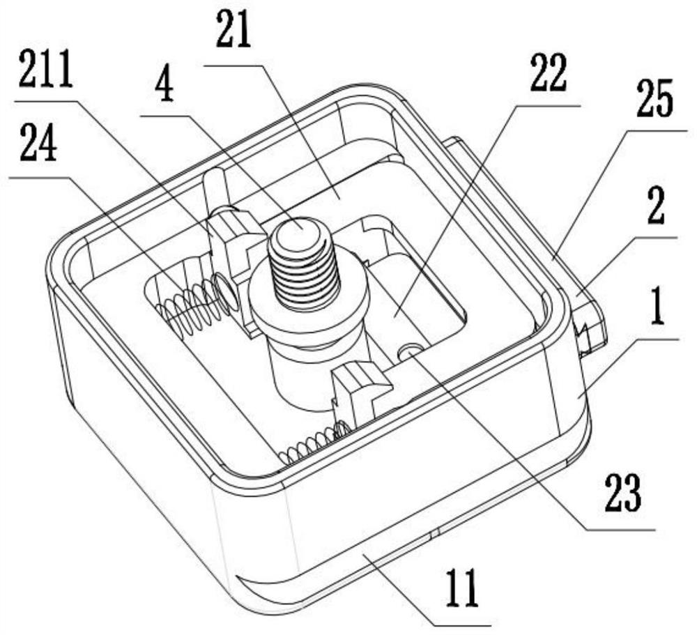
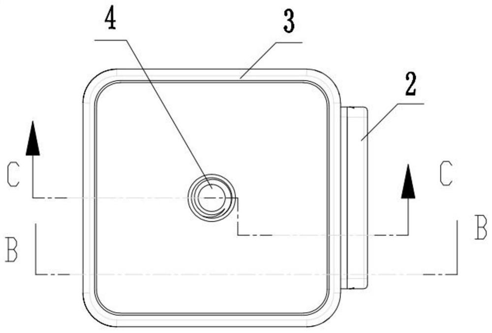
[0022] Such as figure 1 , figure 2 , image 3 , Figure 4 , Figure 5 , Image 6 , Figure 7 , Figure 8 As shown, a quick mount for a camera includes a quick mount base 1, a lock assembly 2, a quick mount plate 3, and a camera fixing screw 4. The quick mount base 1 is a hollow square base without a top surface. The quick loading base 1 is located at the bottom of the quick loading base of the camera, the left and right side walls of the quick loading base 1 are provided with quick loading chute 11, the quick loading base 1 is connected with the camera bracket through the quick loading chute 11, the quick loading A lock window 12 is provided on the front side wall of the base 1. The lock assembly 2 is installed in the inner space of the quick installation base 1 on one side of the lock window 12. The front end of the lock assembly 2 passes th...


PUM


Abstract

The invention provides a camera quick mounting seat. The camera quick mounting seat comprises a quick mounting base, a lock catch assembly, a quick mounting plate and a camera fixing screw, wherein the quick mounting base is located at the lower part of the camera quick mounting seat, quick mounting sliding grooves are formed in the left side wall and the right side wall of the quick mounting base, a lock catch window is formed in the front side wall of the quick mounting base, the lock catch assembly is installed in the inner space, located on one side of the lock catch window, of the quick mounting base, the front end of the lock catch assembly penetrates through the lock catch window and is exposed out of the quick mounting base, the quick mounting plate is arranged on the quick mounting base, the quick mounting plate covers the top of the quick mounting base, a camera fixing screw through hole is formed in the middle of the quick mounting plate, and the front end of the camera fixing screw penetrates through the camera fixing screw through hole upwards from the bottom and is exposed above the quick mounting plate. The camera quick mounting seat has the advantages that a one-waylock structure is adopted, the quick mounting plate is rapid and convenient to install, the structure is simpler, production and installation are easy, and the manufacturing cost is low; and a safetylock piece is arranged, so that the situation that a camera or a triangular frame falls off due to accidental pressing of a lock catch is avoided, and the safety is high.

Description

【Technical field】 [0001] The invention relates to the field of camera accessories, in particular to a camera quick mount. 【Background technique】 [0002] There are usually two connection methods between the camera and the tripod. The first connection method is to directly connect the camera and the tripod. This connection method is inconvenient to operate due to the relatively large volume of the camera and the tripod. It is easy for the equipment to fall; the second connection method is to install a mounting seat with a quick-release plate on the tripod. This type of mounting seat is usually equipped with a lock on both sides to form a two-way press lock. Press the locks on both sides to take out the quick release plate, connect the small quick release plate to the camera, and then put the quick release plate back on the mounting base. This connection method avoids the problem of the first connection method, but two-way The push lock is not convenient in operation, and the...

Claims


Application Information

Patent Timeline
Patent Type & Authority Applications(China)
IPC IPC(8): F16M11/16G03B17/56
CPCF16M11/16G03B17/561
Inventor 吴少林
Owner 深圳市为荣科技有限公司
Why Eureka
Try Eureka