
Intelligent rotary fish expelling device for fish way and method for expelling fish by using device

A rotary and fishway technology, which is applied in water conservancy projects, sea area projects, climate change adaptation, etc., can solve problems such as the inability to collect fish quickly in the fish collection box, low fish passing efficiency, environmental protection and ecological problems, etc. Improve fish efficiency, enhance work reliability, and enhance safety

Pending Publication Date: 2021-02-05
CHANGJIANG SURVEY PLANNING DESIGN & RES
View PDF0 Cites 1 Cited by
  • Summary
  • Abstract
  • Description
  • Claims
  • Application Information

AI Technical Summary

Problems solved by technology

The fish elevator is a form of fishway, which allows fish to pass through hydraulic structures in a faster way; most of the existing fishways are artificial tanks built on river structures, which are difficult to meet the local fish's convection velocity, Due to the requirements of the flow state, under normal circumstances, after fish enter the fishway, they may gather in some areas of the fishway and fail to move forward, resulting in the inability of the fish collection box to quickly collect fish for the next step of transportation, and the fish passing efficiency is low
If artificial intervention is used to collect fish, there will be potential environmental and ecological problems

Method used


Image

  • Intelligent rotary fish expelling device for fish way and method for expelling fish by using device
  • Intelligent rotary fish expelling device for fish way and method for expelling fish by using device
  • Intelligent rotary fish expelling device for fish way and method for expelling fish by using device

Examples


Embodiment Construction

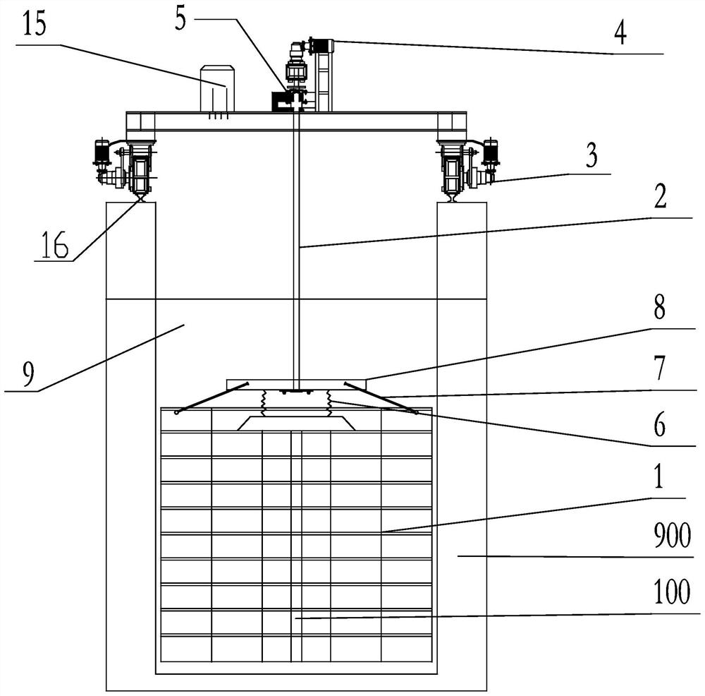
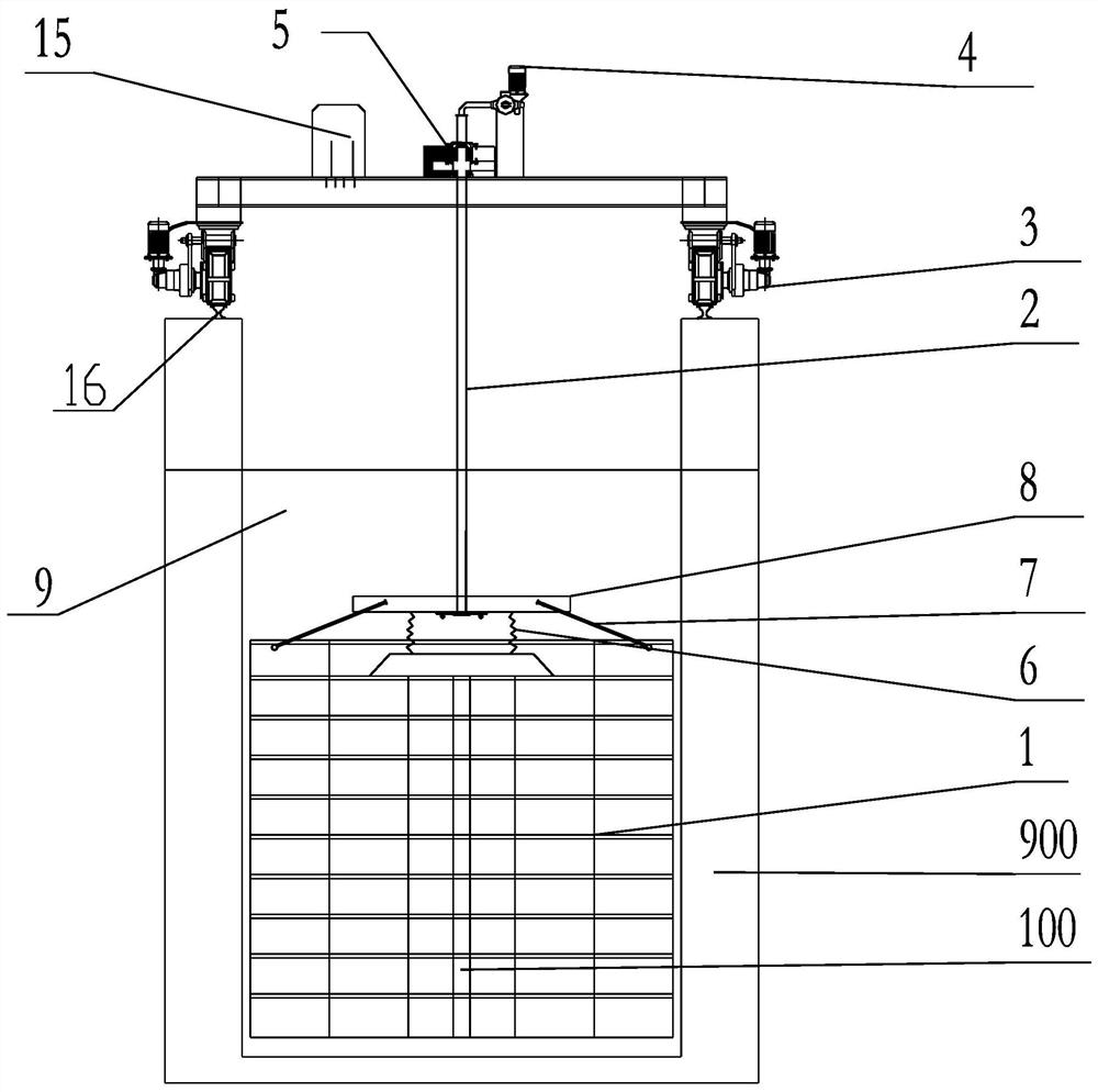
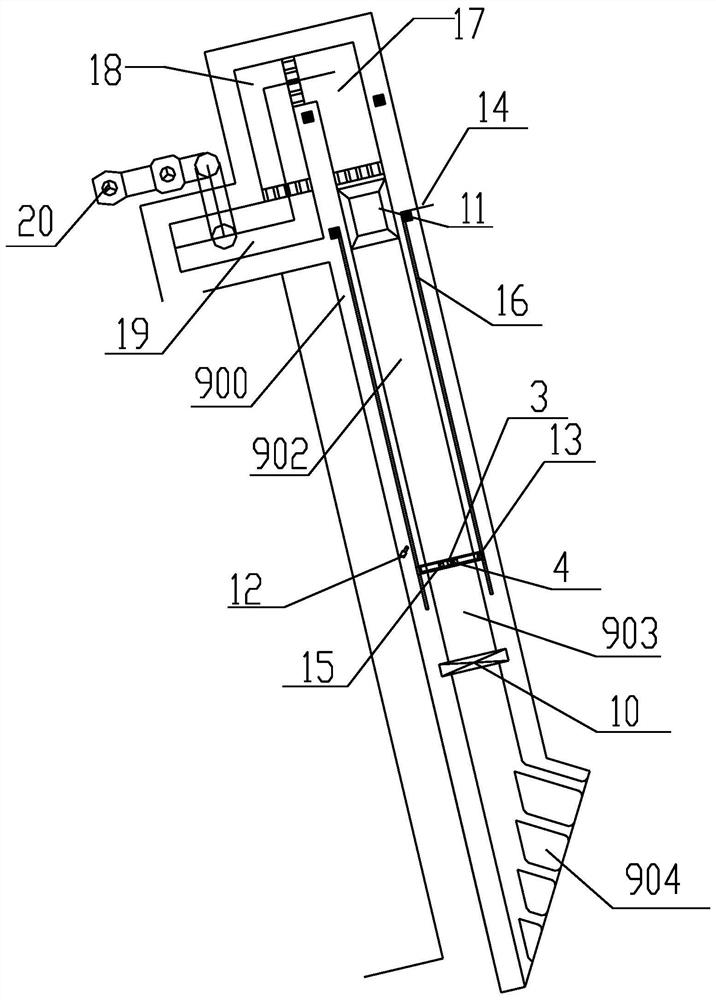
[0036] The present invention will be further described below in conjunction with drawings and embodiments. attached Figure 1 to Figure 9 All are drawings of embodiments, drawn in a simplified manner, and are only used for the purpose of clearly and concisely illustrating the embodiments of the present invention. The following technical solutions shown in the drawings are specific solutions of the embodiments of the present invention, and are not intended to limit the scope of the claimed invention. Based on the embodiments of the present invention, all other embodiments obtained by persons of ordinary skill in the art without creative efforts fall within the protection scope of the present invention.

[0037] In the description of the present invention, it should be understood that the orientations or positional relationships indicated by the terms "upper", "lower", "inner", "outer", "left", "right" etc. are based on those shown in the accompanying drawings. Orientation or ...


PUM


Abstract

The invention discloses an intelligent rotary fish expelling device for a fish way and a method for expelling fish by using the device. The fish expelling device comprises a walking mechanism, a fishblocking electric fence and a fish blocking fence rotating mechanism, wherein the walking mechanism comprises a walking trolley and walking tracks symmetrically distributed on the top surfaces of twoside walls of the fish way; the starting ends of the walking tracks are arranged at positions close to an overhauling folding gate, and the tail ends of the walking tracks extend to a fish collectingcompartment lifting well along the fish way; and the fish blocking electric fence is vertically hung in the fish way through the fish blocking fence rotating mechanism. Before fish expelling, the fishblocking electric fence is parallel to the water flow direction, and downstream fish enters the fish way; and when the fish in the fish way reaches the transportation volume of the fish collecting compartment lifting well, the fish blocking electric fence rotates by 90 degrees to block the inlet of the fish way, and the walking trolley drives the fish blocking electric fence to move and expel thefish in the fish way into a fish collecting compartment. According to the device and the method, the fish is automatically expelled, the fish passing efficiency of the fish way is greatly improved, manual intervention and influence on ecological environmental protection are reduced, and the safety is high.

Description

technical field [0001] The invention relates to the field of water conservancy and hydropower engineering, and more specifically relates to an intelligent rotary fish drive device for driving fish in a fish pass of a hydropower station and a fish drive method using the device. Background technique [0002] In order to meet various requirements such as flood control, irrigation, power generation, shipping, and water supply, it is often necessary to build water conservancy and hydropower engineering buildings on rivers to form reservoirs, raise water levels, and regulate runoff. While the construction of water conservancy and hydropower projects has brought great benefits to human beings, it has also destroyed the biological continuity of the river, blocked the passage of migratory and semi-migratory fish, and reduced the biodiversity of the river. In order to protect natural fishery resources and ensure the continuity and diversity of aquatic ecosystems, the main restoration ...

Claims


Application Information

Patent Timeline
Patent Type & Authority Applications(China)
IPC IPC(8): E02B8/08E02B1/00
CPCE02B1/006E02B8/08E02B8/085Y02A40/60
Inventor 王启行熊绍钧胡吉祥朱世洪李克华罗斌
Owner CHANGJIANG SURVEY PLANNING DESIGN & RES
Learn More