Cylinder sliding device

A sliding device and sliding technology, which is applied in the direction of hoisting device, hoisting device, spring mechanism, etc., can solve the problems of cylinder weight, high cylinder height, high crane hoisting cost, etc., and achieve the effect of reducing hoisting cost

Pending Publication Date: 2021-02-05
JLANGSU DAODA OFFSHORE WIND CONSTR TECH CO LTD
View PDF0 Cites 0 Cited by
  • Summary
  • Abstract
  • Description
  • Claims
  • Application Information

AI Technical Summary

Problems solved by technology

[0002] The diameter of the round steel cylinder at the bottom of the wide and shallow cylindrical foundation is generally 30 to 36 meters. Generally, the cylinder and the upper structure are constructed separately in the construction of the cylindrical foundation. In order to ensure that there is enough space for the construction of the steel cylinder, the built-up The cylinder moves to the upper and lower closing positions. The weight of the completed cylinder is between 350 tons and 450 tons, and the height is about 10 meters. Due to the large diameter, high height and weight of the cylinder, the cost of hoisting with a crane is high; therefore, Need a relatively simple sliding tool to slide up and down to the closed position;

Method used


Image

  • Cylinder sliding device
  • Cylinder sliding device
  • Cylinder sliding device

Examples


Embodiment Construction

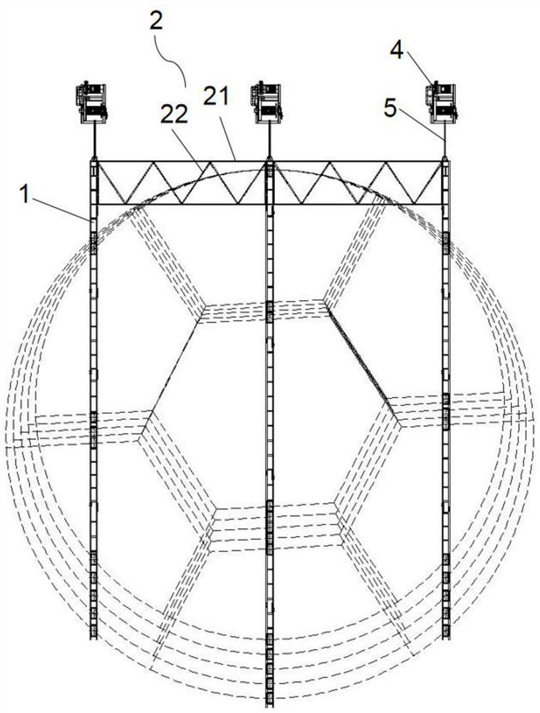
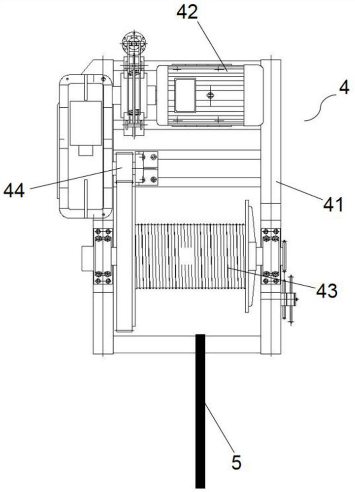
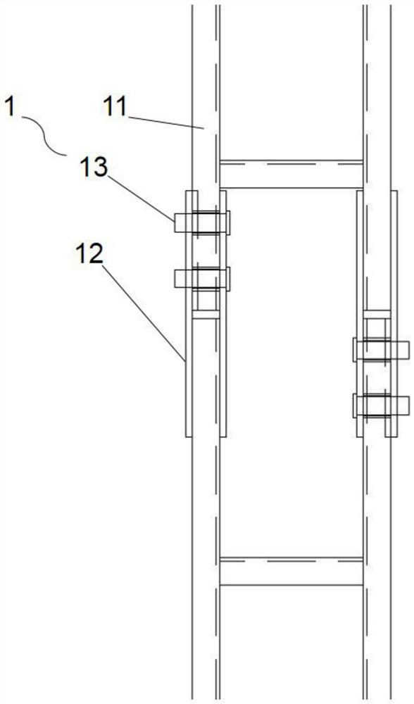
[0026] Such as Figure 1 to Figure 6 As shown, a cylinder sliding device includes several sliding rails 1 arranged in parallel, and a plurality of rollers 32 are provided at the bottom of the sliding rail 1; The end of each sliding rail 1 is also provided with a winch 4, and the winch 4 is located on the base surface, and the winch 4 is connected with the sliding rail 1 by a wire rope 5; the winch 4 includes a motor 42, a roller 43 and a frame 41, the frame 41 is located on the base surface, the motor 42 is located on the frame 41, the two ends of the roller 43 are rotationally connected with the frame 41, the drive shaft of the motor 42 is connected with the end of the roller 43; one end of the wire rope 5 The part is wound on the roller 43. The windlass 4 works at the same time to roll the steel wire rope 5, and drives the sliding rail 1 to move on the base surface through the roller 32 to realize the sliding of the round steel cylinder to the designated position.

[0027]...


PUM


Abstract

The invention provides a cylinder sliding device, and particularly relates to the field of wind power cylinder type foundation tooling. The device comprises several sliding rails arranged in parallel,wherein several rolling wheels are arranged at the lower parts of the sliding rails; one ends of the sliding rails are transversely connected through a connecting frame, a winch is further arranged at the end part of each sliding rail, the winches are arranged on a base surface, and the winches are connected to the sliding rails through steel wire ropes; the winches comprise motors, rolling wheels and racks, wherein the racks are arranged on the base surface, the motors are arranged on the racks, two ends of the rolling wheels are rotationally connected to the racks, and driving shafts of themotors are connected to the end parts of the rolling wheels; and one end parts of the steel wire ropes are wound around the rolling wheels. According to the device, the hoisting cost can be reduced,and a round steel cylinder can safely and reliably slide to a designated position under the condition that a site and equipment are limited.

Description

technical field [0001] The invention belongs to the field of wind electric cylinder-type foundation tooling, and in particular relates to a cylinder sliding device. Background technique [0002] The diameter of the round steel cylinder at the lower part of the wide and shallow cylindrical foundation is generally 30 to 36 meters. Generally, the cylinder and the upper structure are constructed separately in the construction of the cylindrical foundation. In order to ensure that there is enough space for the construction of the steel cylinder, the built The cylinder moves to the upper and lower closing positions. The weight of the completed cylinder is between 350 tons and 450 tons, and the height is about 10 meters. Due to the large diameter, high height and weight of the cylinder, the cost of hoisting with a crane is high; therefore, Need a relatively simple sliding tool to slide up and down to close up position; Contents of the invention [0003] In view of the above disa...

Claims


Application Information

Patent Timeline
Patent Type & Authority Applications(China)
IPC IPC(8): B66F19/00B66D1/60B66D1/12
CPCB66D1/12B66D1/60B66F19/00
Inventor 施金龙刘永刚朱建国黄晓炜
Owner JLANGSU DAODA OFFSHORE WIND CONSTR TECH CO LTD
Why Eureka
Try Eureka