Conveying device for automatic boxing

A transmission device and automatic packing technology, applied in packaging, comprehensive factory control, etc., can solve the problem of large space requirements in the unloading area, achieve the effects of reducing labor load, rationally utilizing production resources, and making manufacturing simple and convenient

Active Publication Date: 2021-02-05
DONGFENG WUHAN IND
View PDF9 Cites 0 Cited by
  • Summary
  • Abstract
  • Description
  • Claims
  • Application Information

AI Technical Summary

Problems solved by technology

[0005] In view of this, it is necessary to provide a transmission device for automatic packing to solve the problem that the existing automatic packing equipment requires a large space in the unloading area

Method used


Image

  • Conveying device for automatic boxing
  • Conveying device for automatic boxing
  • Conveying device for automatic boxing

Examples


Embodiment Construction

[0021] Preferred embodiments of the present invention will be described in detail below in conjunction with the accompanying drawings, wherein the accompanying drawings constitute a part of the application and together with the embodiments of the present invention are used to explain the principle of the present invention and are not intended to limit the scope of the present invention.

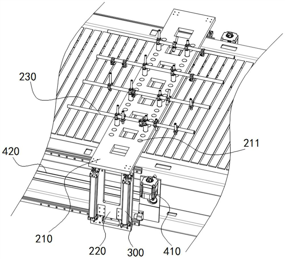
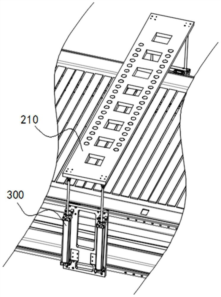
[0022] Such as figure 1 As shown, a transmission device for automatic packing in this embodiment is used for packing parts, including a frame 100, a slide table 200, a first drive assembly 300 and a second drive assembly 400, and the slide table 200 is arranged on Above the frame 100, the first drive assembly 300 is connected with the slide table 200 for driving the slide table 200 to move along a direction perpendicular to the frame 100, and the second drive assembly 400 is connected with the slide table 200 for driving the slide table 200 along the frame 100 to move in the direction of exte...


PUM


Abstract

The invention relates to a conveying device for automatic boxing. The conveying device is used for part boxing and comprises a frame, a sliding table, a first driving assembly and a second driving assembly, wherein a chain plate machine is mounted on the frame; the sliding table comprises a supporting plate and a positioning support; the supporting plate is arranged above the chain plate machine in a crossing manner; the supporting plate is in sliding connection with a frame body; the sliding direction of the supporting plate is the same as the conveying direction of the chain plate machine; the positioning support is fixed above the supporting plate and used for supporting parts; the first driving assembly is in sliding connection with the frame and is provided with a telescopic end; andthe telescopic end of the first driving assembly is vertically arranged, and the top of the telescopic end is fixedly connected with the supporting plate. The problem that existing automatic boxing equipment has high requirements for the space of a discharging area is solved.

Description

technical field [0001] The invention relates to the technical field of thermoforming production automation, in particular to a transmission device for automatic packing. Background technique [0002] In the thermoforming production process, the traditional manual boxing operation is: the unloading robot (manipulator) grabs the formed parts from the press and places them on the chain plate machine, which is transported by the chain plate machine to manual pick-up and boxing . In this process, at least 2 operators need to be assigned to pack the end of the line. When the parts are larger and heavier, the number of operators will increase, and the labor load will also increase accordingly. [0003] With the development trend of intelligent manufacturing, the requirements for production line automation are getting higher and higher. Many production lines adopt automatic boxing solutions. After the unloading robot takes the parts out of the press, it waits outside the press for ...

Claims


Application Information

Patent Timeline
Patent Type & Authority Applications(China)
IPC IPC(8): B65B35/36B65B35/44
CPCB65B35/36B65B35/44Y02P90/02
Inventor 刘鹏王韦聂飞丁恒李康茹承曦徐冬生柯亮李明丽吴娟
Owner DONGFENG WUHAN IND
Why Eureka
Try Eureka