Three-jaw turning tool for machining cuboid workpiece

A cuboid and turning technology, which is applied to metal processing machinery parts, metal processing equipment, positioning devices, etc., can solve problems such as difficult control, large workpiece clamping error, and unguaranteed product quality stability.

Active Publication Date: 2021-02-05
安徽士必达液压器材有限公司
View PDF5 Cites 0 Cited by
  • Summary
  • Abstract
  • Description
  • Claims
  • Application Information

AI Technical Summary

Problems solved by technology

[0002] In the machining industry, many companies mostly use four-jaw chucks as the clamping mechanism when they process cube or cuboid parts. We know that the operation of the four-jaw chuck has the following disadvantages. 1. It takes time to find the center
2. The position of the hole is completely controlled artificially, which is difficult to control
3. The stability of product quality in mass production cannot be guaranteed
4. The technical requirements for operators are relatively high, and generally only experienced masters can operate;
[0003] Especially when the workpiece with a rectangular structure is used, it is inconvenient to clamp and position the workpiece. At the same time, the center of the workpiece deviates from the center of the chuck. When the workpiece is rotated, the eccentricity of the workpiece is serious, and the workpiece is easy to shake, so that the clamping error of the workpiece becomes larger. , the processing progress of the workpiece becomes lower, so a three-jaw turning tool for cuboid workpiece is needed

Method used


Image

  • Three-jaw turning tool for machining cuboid workpiece
  • Three-jaw turning tool for machining cuboid workpiece
  • Three-jaw turning tool for machining cuboid workpiece

Examples


Embodiment Construction

[0027] The following will clearly and completely describe the technical solutions in the embodiments of the present invention with reference to the accompanying drawings in the embodiments of the present invention. Obviously, the described embodiments are only some, not all, embodiments of the present invention.

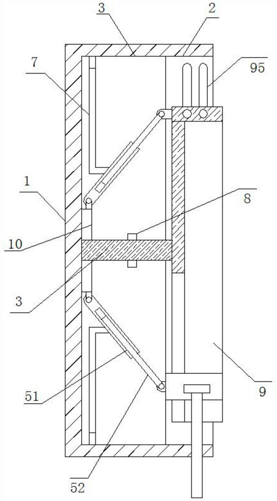
[0028] refer to Figure 1-6 , a kind of tooling for three-jaw turning processing of cuboid workpieces, comprising a main body 1 with a cylindrical structure, one end of the main body 1 is provided with a mounting groove 2 of a rectangular structure, and one end of the mounting groove 2 protruding into the interior of the main body 1 is provided with a shaft coaxial with the main body 1 The storage tank 3 is provided, the inner wall of the storage tank 3 away from the installation tank 2 is fixed with a positioning rod 4 coaxially arranged with the main body 1, and the outer ring of the positioning rod 4 away from the storage tank 3 is fixedly sleeved with a fixed disk...


PUM


Abstract

The invention belongs to the technical field of turning tools, and particularly relates to a three-jaw turning tool for machining a cuboid workpiece. The tool comprises a main body of a cylindrical structure. A mounting groove of a rectangular structure is formed in one end of the main body, and a storage groove coaxial with the main body is formed in the end, stretching into the main body, of themounting groove. A positioning rod coaxial with the main body is fixedly connected to the inner side wall on the side, away from the mounting groove, of the storage groove, the outer ring of the end,away from the storage groove, of the positioning rod is fixedly sleeved with a fixing disc, transverse guide mechanisms symmetrically arranged along the positioning rod are hinged to the two sides ofthe outer ring of the fixing disc, and two vertical guide mechanisms which are symmetrically arranged along the positioning rod are mounted on the sides, close to each other, of two transverse guidemechanisms. With the three-jaw turning tool for machining the cuboid workpiece, eccentric rotation of a workpiece is effectively avoided, the amplitude of vibration of the workpiece due to eccentricity is reduced, the stability of the workpiece after being clamped for machining is improved, the workpiece clamping error is small, and meanwhile tool is suitable for positioning and clamping operationon workpieces of different sizes.

Description

technical field [0001] The invention relates to the technical field of turning tooling, in particular to a tooling for turning a cuboid workpiece with three jaws. Background technique [0002] In the machining industry, many companies mostly use four-jaw chucks as the clamping mechanism when they process cube or cuboid parts. We know that the operation of the four-jaw chuck has the following disadvantages. 1. It takes time to find the center . 2. The position of the hole is completely controlled artificially, which is difficult to control. 3. The stability of product quality during mass production cannot be guaranteed. 4. The technical requirements for operators are relatively high, and generally only experienced masters can operate; [0003] Especially when the workpiece with a rectangular structure is used, it is inconvenient to clamp and position the workpiece. At the same time, the center of the workpiece deviates from the center of the chuck. When the workpiece is ro...

Claims


Application Information

Patent Timeline
IPC IPC(8): B23Q3/12
CPCB23Q3/12B23Q2703/10
Inventor 石春炳
Owner 安徽士必达液压器材有限公司
Why Eureka
Try Eureka