A sheet metal welding equipment
A welding equipment and sheet metal technology, applied in the field of welding equipment, can solve the problems of unstable quality of welding products and low welding efficiency
- Summary
- Abstract
- Description
- Claims
- Application Information
AI Technical Summary
Problems solved by technology
Method used
Image

Examples
Embodiment 1
[0080] A sheet metal welding equipment, such as figure 1 As shown, it includes a bottom plate 1, a first support frame 2, a servo motor 3, a placement mechanism 4, a clamping mechanism 5, a transmission mechanism 6, a welding mechanism 7 and a feeding mechanism 8, and a first support is provided on the right rear side of the top of the bottom plate 1 Frame 2, the top of the first support frame 2 is provided with a servo motor 3, the front side of the bottom plate 1 is provided with a placement mechanism 4, the placement mechanism 4 is provided with a clamping mechanism 5, the left side of the top of the bottom plate 1 is provided with a transmission mechanism 6, and the bottom plate 1 A welding mechanism 7 is provided in the middle of the top, and a feeding mechanism 8 is provided on the rear side of the top of the bottom plate 1 .
[0081] The staff places the sheet metal in the feeding mechanism 8, then starts the servo motor 3 and the welding mechanism 7 to work, the servo ...
Embodiment 2
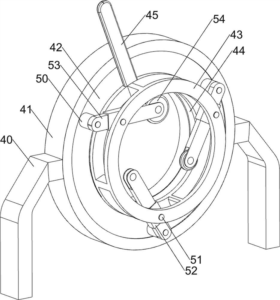
[0083] On the basis of Example 1, such as figure 1 and Figure 2-5 As shown, the placement mechanism 4 includes a first support plate 40, a support basket 41, a connecting ring 42, a connecting frame 43, a threaded spring 44 and a first connecting rod 45, and the front side of the bottom plate 1 is symmetrically provided with the first support plate 40, A supporting basket 41 is provided between the first supporting plates 40, and a connecting ring 42 is provided inside the supporting basket 41, and a connecting frame 43 is arranged in a rotating manner in the connecting ring 42, and a threaded spring 44 is provided between the connecting ring 42 and the connecting frame 43, The threaded spring 44 is located in the connecting ring 42 , and the connecting frame 43 is provided with a first connecting rod 45 .
[0084] The clamping mechanism 5 includes a fixed block 50, a second connecting rod 51, a guide block 52, a slide plate 53, and a first roller 54. The front side of the c...
Embodiment 3
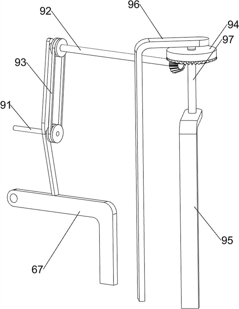
[0092] On the basis of Example 2, such as figure 1 and Figure 6 As shown, a toggling mechanism 9 is also included. A toggling mechanism 9 is provided on the left front side of the top of the bottom plate 1. The toggling mechanism 9 includes a second bevel gear 90, an eighth rotating shaft 91, a ninth rotating shaft 92, and a third pulley assembly 93. , the 3rd bevel gear 94, the 3rd support plate 95, the 4th support plate 96, the 10th rotating shaft 97 and the wedge-shaped block 98, the rotatable type is provided with the 8th rotating shaft 91 on the second supporting frame 67, the 8th rotating shaft 91 and the seventh A second bevel gear 90 is provided on the rotating shaft 81, and the two second bevel gears 90 are meshed with each other. The ninth rotating shaft 92 is rotatably arranged on the second support frame 67, and a second bevel gear 92 is arranged between the eighth rotating shaft 91 and the ninth rotating shaft 92. The third pulley assembly 93, the bottom left fr...
PUM
 Abstract
Description
Claims
Application Information
 - Generate Ideas
- Intellectual Property
- Life Sciences
- Materials
- Tech Scout
- Unparalleled Data Quality
- Higher Quality Content
- 60% Fewer Hallucinations
Browse by: Latest US Patents, China's latest patents, Technical Efficacy Thesaurus, Application Domain, Technology Topic, Popular Technical Reports.
© 2025 PatSnap. All rights reserved.Legal|Privacy policy|Modern Slavery Act Transparency Statement|Sitemap|About US| Contact US: help@patsnap.com