Waste industrial cable recovery device

A recovery device and industrial technology, applied in the direction of electronic waste recovery, recycling technology, circuits, etc., can solve the problems of general cleaning effect and single operation method, and achieve the effect of improving the cleaning effect

Inactive Publication Date: 2021-02-05
张爱莲
View PDF5 Cites 2 Cited by
  • Summary
  • Abstract
  • Description
  • Claims
  • Application Information

AI Technical Summary

Problems solved by technology

In the process of traditional industrial cable recycling, most cable cleaning devices only use simple rotating brushes to clean them. The operation method is relatively simple, and the actual cleaning effect is relatively general, so there are certain limitations.

Method used


Image

  • Waste industrial cable recovery device
  • Waste industrial cable recovery device
  • Waste industrial cable recovery device

Examples


Embodiment 1

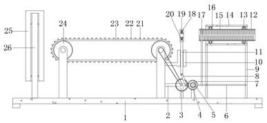
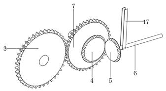
[0029] refer to Figure 1-4 , a waste industrial cable recovery device, comprising a base plate 1 with legs welded at the four corners of the bottom outer wall, a fixed rod 26 is vertically welded on both sides of one end of the top outer wall of the base plate 1, and the outer walls of the fixed rod 26 are rotated by bearings A guide roller 25 is connected, and a drag mechanism is installed on the top outer wall of the base plate 1, and the drag mechanism includes a fixed column fixedly installed on the base plate 1, and the corresponding two fixed columns are connected to the same shaft through bearing rotation, and The outer wall of the shaft rod is connected with a roller body 24 by a key, and the outer wall of the roller body 24 is sleeved with the same transmission rail belt 23, and the outer wall of the transmission rail belt 23 is bonded with rubber convex strips 21 distributed at equal distances, and the rubber convex strips There is a strip groove 22 at the central a...

Embodiment 2

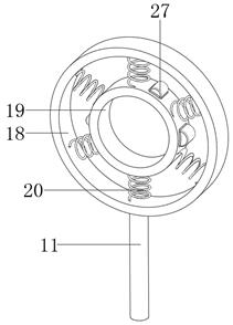
[0040] refer to Figure 5 , a waste industrial cable recovery device, compared with Embodiment 1, this embodiment also includes that the inner wall of the inner ring 19 is fixedly equipped with rubber wipers 28 distributed equidistantly, and the rubber wipers 28 are far away from the end of the inner ring 19 All have triangular notches; through the rubber wiper 28 arranged on the inner ring 19, in cooperation with the triangular notches, the cable surface can be touched and rubbed during the vibration process of the cable itself.

[0041] When the present invention is used: the rubber wiper 28 arranged on the inner ring 19 cooperates with the triangular notch to touch and rub the cable surface during the vibration process of the cable itself, so as to further improve the cleaning effect of the cable surface the goal of.


PUM


Abstract

The invention belongs to the technical field of industrial cable recycling, particularly relates to a waste industrial cable recycling device, and provides the following scheme for solving the problems that in the traditional industrial cable recycling process, a cable cleaning device is generally simple in structural design, most of cable cleaning devices only use a rotating simple brush for cleaning, and the cleaning effect is general. The device comprises a base plate, supporting legs are welded to the four corners of the outer wall of the bottom of the base plate, and fixing rods are vertically welded to the two sides of one end of the outer wall of the top of the base plate. By means of a dragging mechanism, when an outer winding mechanism winds and drags a cable, a transmission railbelt and a roller body can be driven to rotate under the action of friction force provided by rubber protruding strips with strip-shaped grooves, meanwhile, a transmission main fluted disc is driven to rotate through a belt, under the action of a transmission rod and a driving rod, a vibration ring is driven to quickly reciprocate up and down, so that the cable at the center is driven to vibrate up and down, and soil attached to the surface of the cable is shaken off.

Description

technical field [0001] The invention relates to the technical field of recycling industrial cables, in particular to a recycling device for waste industrial cables. Background technique [0002] Industry is a product processing and manufacturing industry. Industry is the product of social division of labor and has gone through several development stages of handicraft industry and machine industry. Industry is an integral part of the secondary industry, which is mainly divided into light industry and heavy industry. A rope-like cable usually made of several wires or groups of wires twisted together, each group of wires is insulated from each other, and is often twisted around a center, and the entire outside is covered with a highly insulating coating. The cable has the characteristics of internal electrification and external insulation. Industrial wire and cable includes single-core wire and cable, rubber cable, shielded control cable, flame-retardant cable, fire-resistant...

Claims


Application Information

Patent Timeline
Patent Type & Authority Applications(China)
IPC IPC(8): B08B1/02B08B1/00B08B7/02B08B13/00H01B15/00B65H54/02
CPCB08B1/02B08B1/002B08B7/02B08B13/00H01B15/00B65H54/02B65H2701/34Y02W30/82
Inventor 张爱莲
Owner 张爱莲
Why Eureka
Try Eureka