Overflow type dental impression tray
A technique for dental impressions and trays, applied in dentistry, dental prostheses, compression molding cups, etc., can solve the problems of complicated operations, reduced comfort, and low work efficiency, and achieve the effect of saving cleaning time and improving efficiency
- Summary
- Abstract
- Description
- Claims
- Application Information
AI Technical Summary
Problems solved by technology
Method used
Image
Examples
Embodiment 1
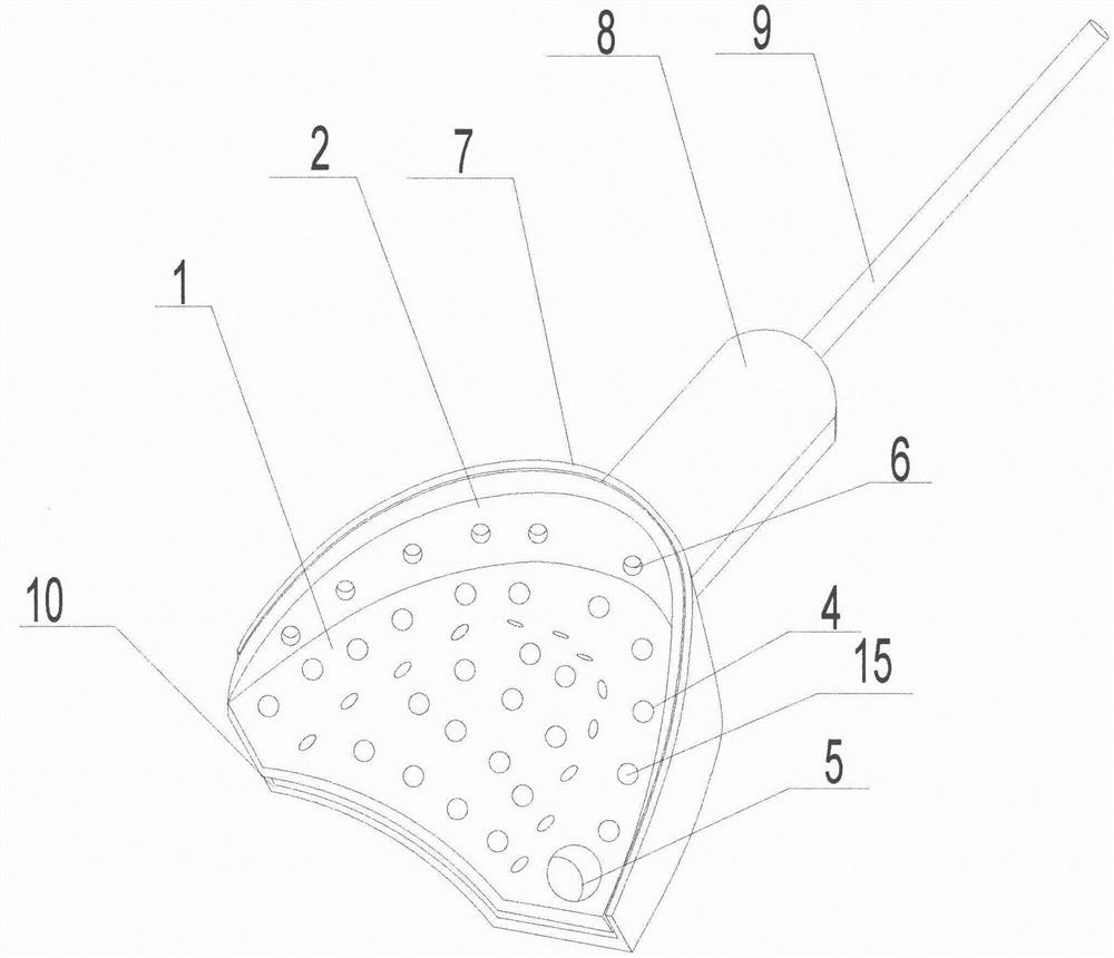
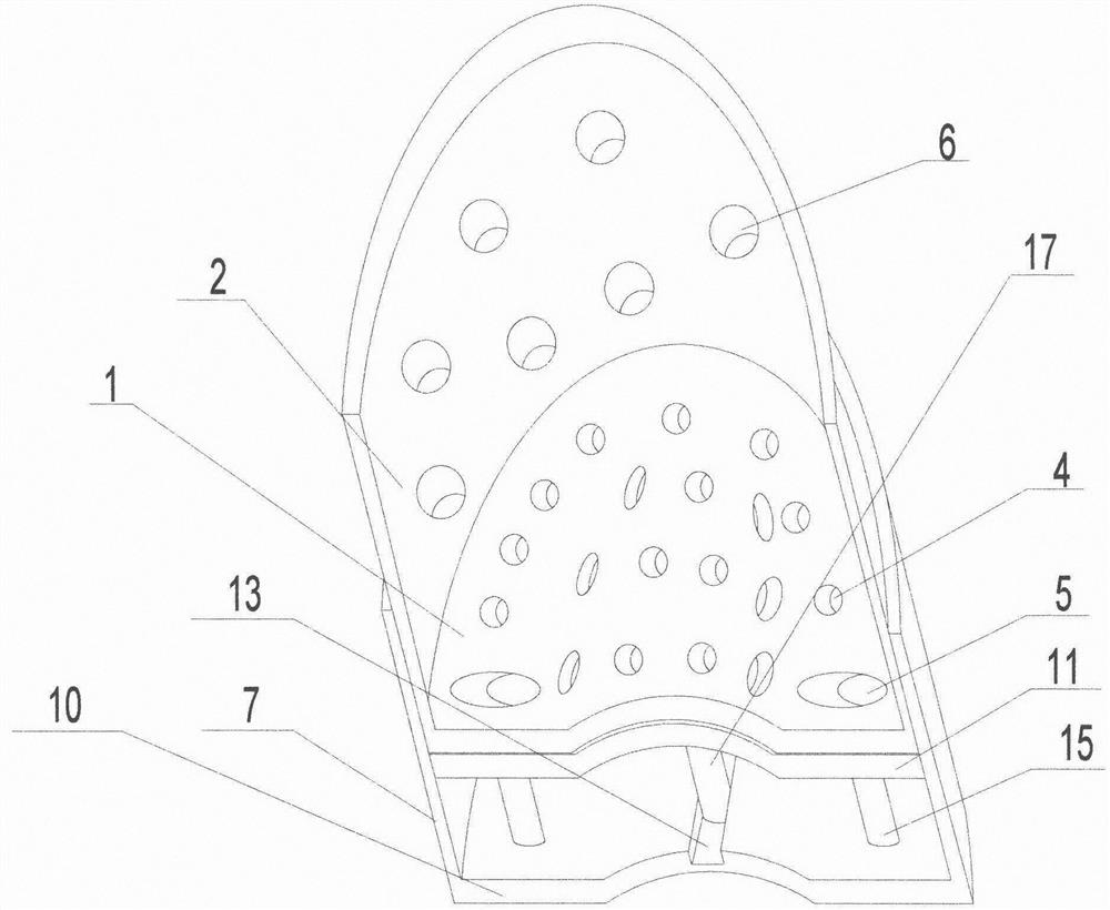
[0042] The tray of the device includes a first bottom plate 1 and a first outer side wall 2 arranged along the outer edge of the first bottom plate 1. The middle part of the first bottom plate 1 is provided with an arched protrusion, and the arched protrusion is connected to the inner wall of the first outer side wall 2. A channel that can accommodate the upper dental arch is formed. The first bottom plate 1 is provided with a number of first mesh holes 4, and the first outer wall 2 is provided with a number of second mesh holes 6. Between the first outer wall and the first bottom plate The angle between them is 90 degrees. When in use, the impression material is filled in the groove surrounded by the arched protrusion of the first bottom plate and the inner wall of the first outer side wall 2 .
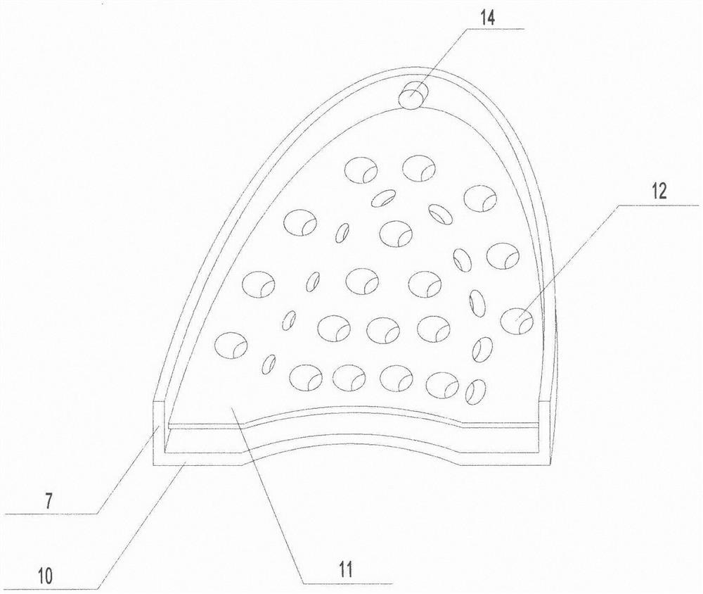
[0043] Such as figure 1 As shown, a third bottom plate 10 is provided below the first bottom plate 1. The shape of the third bottom plate 10 is the same as that of the first bottom ...
Embodiment 2
[0048] In this embodiment, the structure of the second bottom plate is as Figure 4 As shown, the first sliding assembly includes a rotating rod 9 and a connecting rod 17, one end of the connecting rod 17 is connected to the lower end of the second bottom plate 11, the other end of the connecting rod 17 is vertically connected to the rotating rod 9, and the connecting rod and the rotating rod pass through the sleeve barrel connection, so the rotating rod will not drive the connecting rod to rotate when rotating, and at the same time, the two ends of the sleeve on the rotating rod are provided with baffles, so the rotating rod can drive the connecting rod and the connecting rod when moving in the direction perpendicular to the connecting rod The second base plate moves together. The structure of the third bottom plate is as follows Figure 6 As shown, the third bottom plate 10 is provided with a groove 13 for placing the rotating rod 9, the outer surface of the second outer si...
Embodiment 3
[0052] On the basis of Example 2, such as Figure 10As shown, the piercing column 15 includes a tip and a bottom end, the bottom end is a cylinder with the same diameter as the inner diameter of the first mesh 4, the tip is a cone whose diameter gradually decreases from bottom to top, and the side surface of the bottom end is a tooth surface. The first mesh 4 is in the shape of a truncated cone with a diameter at the lower end smaller than that at the upper end, and the third mesh 12 is in the shape of a truncated cone with a diameter at the lower end greater than that at the upper end. When in use, the extruded impression material flows into the first mesh, and since the first mesh and the third mesh correspond to and touch, the impression material then flows into the third mesh and moves in the horizontal direction When the second bottom plate is used, the position where the second bottom plate acts on the impression material is the position between the first mesh and the th...
PUM
| Property | Measurement | Unit |
|---|---|---|
| Height | aaaaa | aaaaa |
| Thickness | aaaaa | aaaaa |
| Thickness | aaaaa | aaaaa |
Abstract
Description
Claims
Application Information
 - R&D
- Intellectual Property
- Life Sciences
- Materials
- Tech Scout
- Unparalleled Data Quality
- Higher Quality Content
- 60% Fewer Hallucinations
Browse by: Latest US Patents, China's latest patents, Technical Efficacy Thesaurus, Application Domain, Technology Topic, Popular Technical Reports.
© 2025 PatSnap. All rights reserved.Legal|Privacy policy|Modern Slavery Act Transparency Statement|Sitemap|About US| Contact US: help@patsnap.com


