
Induction furnace

A technology of induction furnace and coil, applied in the field of induction furnace, to achieve the effect of suppressing partial discharge

Active Publication Date: 2021-02-02
FUJI ELECTRIC CO LTD
View PDF9 Cites 0 Cited by
  • Summary
  • Abstract
  • Description
  • Claims
  • Application Information

AI Technical Summary

Problems solved by technology

Therefore, in the conventional induction furnace, the voltage applied to the coil is limited to about 5kV, and further increase in voltage is desired.

Method used


Image

  • Induction furnace
  • Induction furnace
  • Induction furnace

Examples


Embodiment Construction

[0035] Hereinafter, embodiment of the induction furnace of this invention is demonstrated in detail based on drawing. In addition, the present invention is not limited by this embodiment.

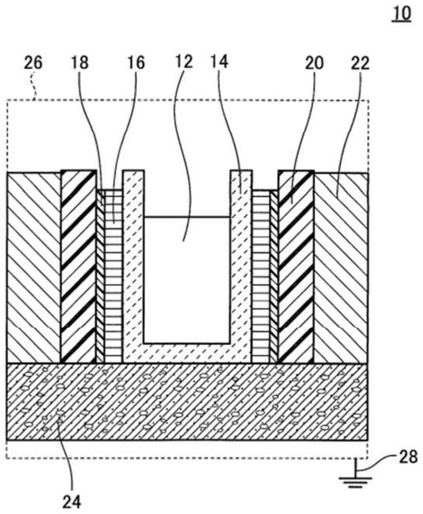
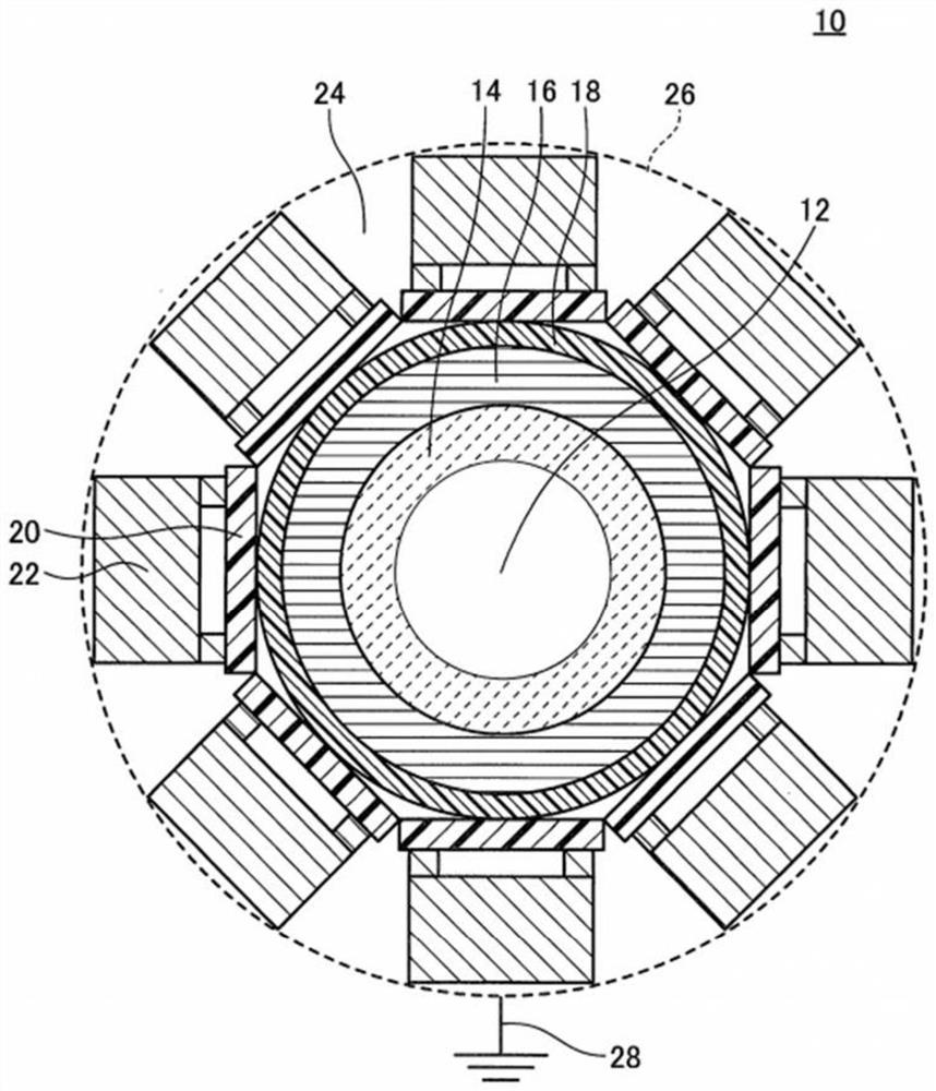
[0036] figure 1 It is a side schematic sectional view which shows the induction furnace 10 which is embodiment of this invention, figure 2 It is a schematic top view of the induction furnace 10.

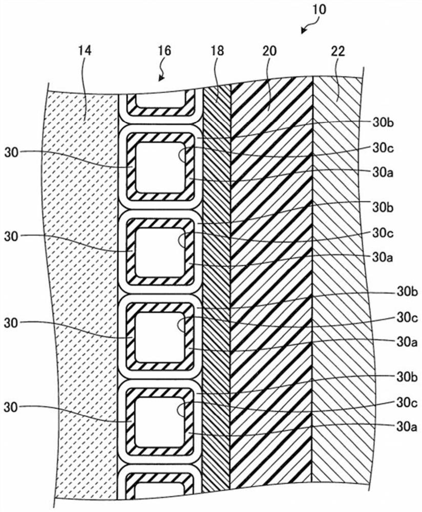
[0037] Such as figure 1 with figure 2 As shown, the induction furnace 10 includes: a crucible 14, the crucible accommodates the heated material 12; a coil 16 for induction, the coil for induction is wound around the periphery of the crucible 14; a conductive layer 18, the conductive layer The outer circumference of the coil 16 is covered; the buffer material 20 which covers the outer circumference of the conductive layer 18; Crucible 14 , coil 16 , conductive layer 18 , buffer material 20 and yoke 22 are disposed on lower castable 24 . The induction furnace 10 as a whole is covered with a ...


PUM


Abstract

Provided is an induction furnace capable of further increasing the voltage applied to a coil. An induction furnace (10) is provided with: a crucible (14) that houses a material (12) to be heated; a coil (16) that is wound around the outer periphery of the crucible (14) and has an insulating coating film; a conductive layer (18) that covers the outer peripheral surface of the coil (16); and a yoke(22) that holds the coil (16) from the outer peripheral side with the conductive layer (18) interposed therebetween. The conductive layer (18) and the yoke (22) are grounded. The conductive layer (18)is a conductive resin or a conductive adhesive, and is in close contact with the insulating film of the coil (16). A conductive buffer material (20) is included between the conductive layer (18) andthe yoke (22), and the conductive layer (18) is grounded via the buffer material (20) and the yoke (22).

Description

technical field [0001] The present invention relates to an induction furnace which uses a crucible to heat a material to be heated. Background technique [0002] There is known an induction furnace in which a coil is wound around the outer periphery of a crucible. High-frequency high-voltage alternating current is applied to the coil to generate electromagnetic induction, and an eddy current is generated inside the heated material accommodated in the crucible, enabling efficient melting. The material to be heated is molten metal, for example. The crucible inhibits heat conduction other than metal melting. The coil is insulated by an insulating material such as an insulating film or an insulating plate. [0003] As such an induction furnace, the induction furnace described in patent document 1 is mentioned, for example. The induction furnace described in Patent Document 1 is a small induction furnace used in a vacuum vessel. On the other hand, in the case of a large indu...

Claims


Application Information

Patent Timeline
Patent Type & Authority Applications(China)
IPC IPC(8): F27B14/06H05B6/36
CPCF27B14/061H05B6/365H05B6/367Y02P10/25
Inventor 增井秀好
Owner FUJI ELECTRIC CO LTD
Learn More