
Device for inertial ejection of unmanned aerial vehicle

A technology of unmanned aerial vehicles and machine inertia, which is applied in the field of aircraft launch, and can solve problems such as complex ejection technology, low initial velocity of unmanned aerial vehicles, and inconvenient energy supplementation

Active Publication Date: 2021-02-02
THE 21TH RES INST OF CHINA ELECTRONIC TECH GRP CORP
View PDF7 Cites 0 Cited by
  • Summary
  • Abstract
  • Description
  • Claims
  • Application Information

AI Technical Summary

Problems solved by technology

[0003] For the above-mentioned various launch methods: using manual ejection, only small and lightweight drones can be ejected. The service life is limited, and the initial velocity of the UAV is low; although the air / hydraulic ejection system can enable the UAV to obtain a higher initial velocity, the structure of the air / hydraulic ejection system is relatively complicated, and it is inconvenient to replenish energy; the electromagnetic ejection system is It needs to use a long track, and its ejection technology is relatively complicated. Therefore, due to the constraints of power supply, motor and control technology, its popularity is low; the technology of gas ejection and shell ejection is complicated, and there are unsafe factors such as fire and noise; the parent machine / The bomb release method requires more complicated conditions for the take-off of the parent aircraft or the launch conditions of the mother bomb, and the launch cost is high

Method used


Image

  • Device for inertial ejection of unmanned aerial vehicle
  • Device for inertial ejection of unmanned aerial vehicle
  • Device for inertial ejection of unmanned aerial vehicle

Examples


Embodiment Construction

[0035] The present invention will be described in detail below with reference to the accompanying drawings and examples. Each example is provided by way of explanation of the invention, not limitation of the invention. In fact, those skilled in the art will recognize that modifications and variations can be made in the present invention without departing from the scope or spirit of the invention. For example, features illustrated or described as part of one embodiment can be used on another embodiment to yield a still further embodiment. Therefore, it is intended that the present invention includes such modifications and variations as come within the scope of the appended claims and their equivalents.

[0036] In the description of the present invention, the terms "longitudinal", "transverse", "upper", "lower", "front", "rear", "left", "right", "vertical", "horizontal", " The orientations or positional relationships indicated by "top", "bottom", etc. are based on the orienta...


PUM


Abstract

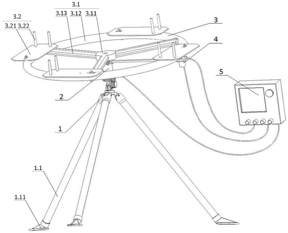
The device comprises a device for inertial ejection of an unmanned aerial vehicle comprising a launching height and angle adjusting mechanism, an inertia driving mechanism, an inertia rotation and mounting fixing mechanism of the unmanned aerial vehicle, a triggering unlocking mechanism of the unmanned aerial vehicle and a controller. The ejection height and angle adjusting mechanism is used for adjusting the initial launching height and launching angle of the unmanned aerial vehicle. The inertia driving mechanism is used for providing power, driving inertia rotation of the unmanned aerial vehicle and rotation of the mounting fixing mechanism, and then providing inertia ejection force for the unmanned aerial vehicle. The fixed height, angle and unlocking opportunity of the unmanned aerialvehicle are controlled through the launching height and angle adjusting mechanism, the unmanned aerial vehicle triggering and unlocking mechanism and the controller, so that the unmanned aerial vehicle obtains the required initial ejection angle and speed. The inertia ejection speed of the unmanned aerial vehicle can be controlled, and unmanned aerial vehicle ejection of different loads is achieved. The device is reasonable in structural design, simple in control mode, convenient in energy supply, high in launching flexibility and high in continuous launching capacity.

Description

technical field [0001] The present invention relates to the technical field of aircraft launching, and more specifically relates to a device for inertial ejection of drones. Background technique [0002] At present, the launch of UAVs mainly adopts manual ejection, ejection, parent machine / projectile delivery, etc. The ejection is divided into elastic element ejection, gas / hydraulic ejection, electromagnetic ejection, gas ejection, etc. [0003] For the above-mentioned various launch methods: using manual ejection, only small and lightweight drones can be ejected. The service life is limited, and the initial velocity of the UAV is low; although the air / hydraulic ejection system can enable the UAV to obtain a higher initial velocity, the structure of the air / hydraulic ejection system is relatively complicated, and it is inconvenient to replenish energy; the electromagnetic ejection system is It needs to use a long track, and its ejection technology is relatively complicated....

Claims


Application Information

Patent Timeline
IPC IPC(8): B64F1/04
CPCB64F1/04
Inventor 郑文鹏方晓强肖渊海杨素香陆英
Owner THE 21TH RES INST OF CHINA ELECTRONIC TECH GRP CORP
Learn More