Long-focus infrared synchronous imaging lens
A synchronous imaging and infrared technology, which is applied in the field of telephoto infrared synchronous imaging lens, can solve the problems that the visible spectrum and infrared spectrum cannot be confocal, and achieve the effects of reducing the tolerance sensitivity of the system, smoothing the light trend, and realizing distortion
- Summary
- Abstract
- Description
- Claims
- Application Information
AI Technical Summary
Problems solved by technology
Method used
Image

Examples
Embodiment approach 1
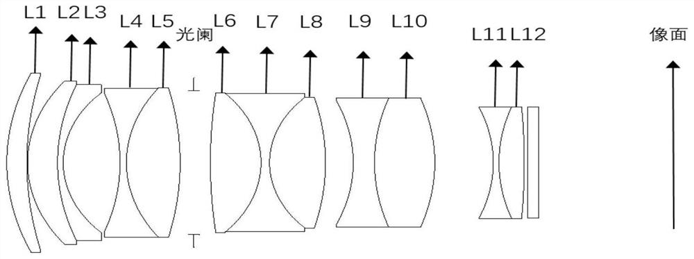
[0071] figure 1 It is a schematic diagram showing the structure of the telephoto infrared synchronous imaging lens according to Embodiment 1 of the present invention.
[0072] The following table 2 lists the relevant parameters of each lens of the present embodiment, including surface type, radius of curvature, thickness, refractive index of material, Abbe number:
[0073] Face number surface type radius of curvature thickness Refractive index Abbe number S1 sphere 39.63 3.01 1.80 41.02 S2 sphere 70.68 0.10 S3 sphere 23.83 4.80 1.83 37.22 S4 sphere 40.13 0.80 1.68 31.16 S5 sphere 17.82 8.01 S6 sphere -47.02 0.90 1.71 29.50 S7 sphere 20.73 7.57 1.84 23.78 S8 sphere -57.44 1.94 S9(Stop) sphere Infinity 2.32 S10 sphere 90.47 9.14 1.61 55.77 S11 sphere -17.33 1.20 1.67 32.17 S12 sphere 15.70 7.89 1.61 55.77 S13 sphere -45.81 3...
Embodiment approach 2
[0078] Figure 6 It is a schematic diagram showing the structure of the telephoto infrared simultaneous imaging lens according to Embodiment 2 of the present invention.
[0079] The following table 3 lists the relevant parameters of each lens of this embodiment, including surface type, radius of curvature, thickness, refractive index of material, Abbe number:
[0080] Face number surface type radius of curvature thickness Refractive index Abbe number S1 sphere 40.68 2.88 1.85 23.80 S2 sphere 96.16 0.10 S3 sphere 31.64 5.55 1.75 51.20 S4 sphere 1288.01 1.52 S5 sphere -400.58 0.80 1.67 34.20 S6 sphere 20.00 5.85 S7 sphere -42.81 0.8 1.68 31.16 S8 sphere 49.47 3.08 1.8 22.70 S9 sphere -160.97 5.14 S10 (Stop) sphere Infinity 2.24 S11 sphere 60.45 8.37 1.61 63.39 S12 sphere -30.46 0.80 1.68 31.16 S13 sphere 16.08 7.17 1.61 ...
Embodiment approach 3
[0085] Figure 11 It is a schematic diagram showing the structure of the telephoto infrared synchronous imaging lens according to Embodiment 3 of the present invention.
[0086] The following table 4 lists the relevant parameters of each lens of this embodiment, including surface type, radius of curvature, thickness, refractive index of material, Abbe number:
[0087] Face number surface type radius of curvature thickness Refractive index Abbe number S1 sphere 40.00 3.35 1.80 41.02 S2 sphere 90.02 0.10 S3 sphere 23.49 3.20 1.83 42.74 S4 sphere 25.63 1.60 S5 sphere 45.81 0.80 1.64 33.84 S6 sphere 17.70 7.98 S7 sphere -30.07 0.80 1.66 33.05 S8 sphere 29.01 6.55 1.80 25.46 S9 sphere -42.06 1.95 S10 (Stop) sphere Infinity 2.00 S11 sphere 90.05 7.00 1.60 65.47 S12 sphere -17.43 0.80 1.69 30.05 S13 sphere 16.55 8.36 1.60 65....
PUM
 Abstract
Description
Claims
Application Information
 - R&D
- Intellectual Property
- Life Sciences
- Materials
- Tech Scout
- Unparalleled Data Quality
- Higher Quality Content
- 60% Fewer Hallucinations
Browse by: Latest US Patents, China's latest patents, Technical Efficacy Thesaurus, Application Domain, Technology Topic, Popular Technical Reports.
© 2025 PatSnap. All rights reserved.Legal|Privacy policy|Modern Slavery Act Transparency Statement|Sitemap|About US| Contact US: help@patsnap.com