
Rapid cloth coating device for garment making

A coating device and cloth technology, which is applied to the surface coating liquid device, coating, pretreatment surface, etc., can solve the problems of redundant structure of the coating device, difficulty in device assembly, high size requirements, etc., and achieve improvement The effect of convenient feeding, low cost and high flexibility

Inactive Publication Date: 2021-01-29
江门市祥康纺织制衣有限公司
View PDF0 Cites 0 Cited by
  • Summary
  • Abstract
  • Description
  • Claims
  • Application Information

AI Technical Summary

Problems solved by technology

[0002] A very important step in the garment manufacturing process is the coating device. However, most of the traditional coating devices have redundant structures. It is feasible, but the size requirements of each component are very high, because once the design is wrong, the device will be extremely difficult to assemble, or even impossible to assemble. Therefore, it is very meaningful to design a simple and convenient assembly line fast coating device

Method used


Image

  • Rapid cloth coating device for garment making
  • Rapid cloth coating device for garment making
  • Rapid cloth coating device for garment making

Examples


Embodiment 1

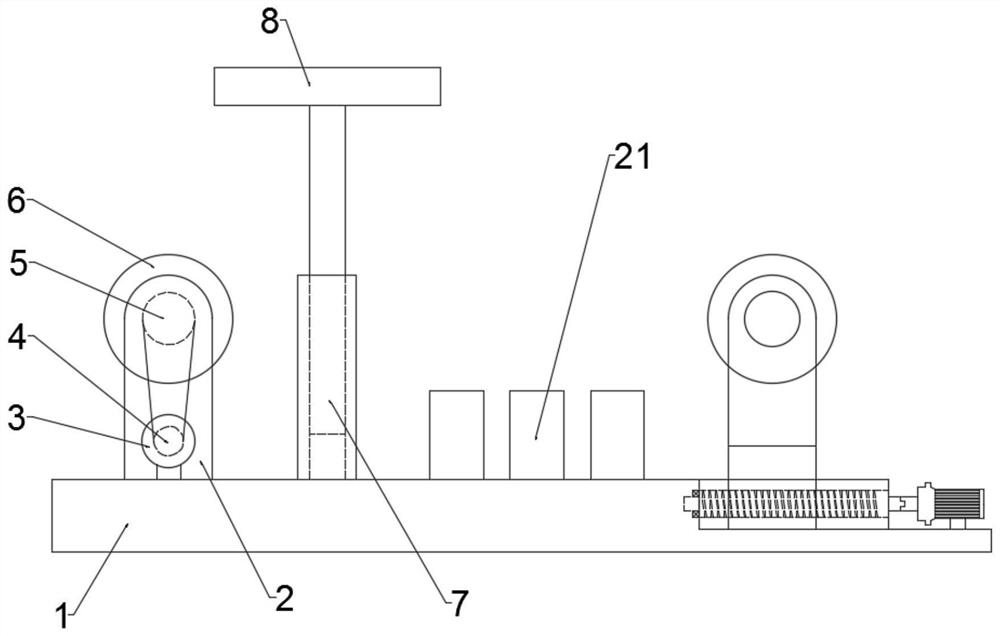
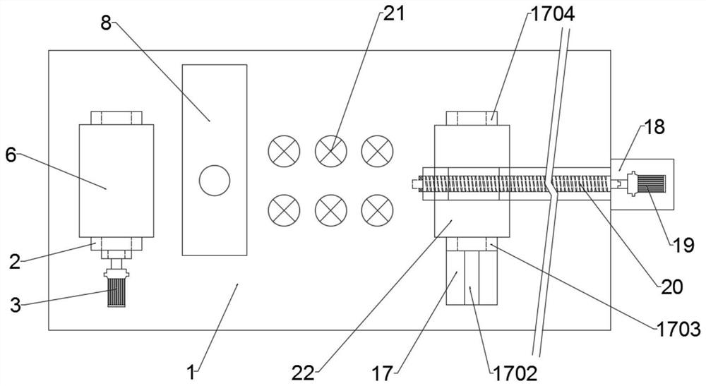
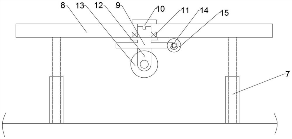
[0022] see Figure 1-5 , in an embodiment of the present invention, a cloth rapid coating device for clothing production includes a first base 1, a power device is provided on the upper left side of the first base 1, and the power device includes a first roller seat 2. There are two first roller seats 2, and one of the first roller seats 2 is detachably connected to the first base 1 for easy assembly; a first roller shaft 6 is arranged between the first roller seats 2, The first roller shaft 6 is rotationally connected with the first roller base 2, and one end of the first roller shaft 6 is provided with a first motor 3, and the output shaft of the first motor 3 is provided with a first Pulley 4, detachably connected between the first pulley 4 and the output shaft of the first motor 3, one end of the first roller shaft 6 is provided with a second pulley 5, the first pulley A belt is provided between 4 and the second pulley 5;

[0023] Further, a feeding device is provided on...

Embodiment 2

[0027] see Figure 1-2 The difference from Embodiment 1 is that in the embodiment of the present invention, a drying cylinder 21 is provided between the coating device and the feeding device.

[0028] The working principle of the embodiment of the present invention is: different from Embodiment 1, in this embodiment, a drying cylinder 21 is provided between the coating device and the feeding device, and the drying cylinder 21 can make the coating dry faster. accelerate.

[0029] The electrical components appearing in this article are all connected with the external main controller and 220V mains electricity, and the main controller can be a conventional known device that plays a control such as a computer.


PUM


Abstract

The invention relates to the field of garment making technology processing equipment, and particularly discloses a rapid cloth coating device for garment making. The device comprises a first base, a power device is arranged on the left side of the upper portion of the first base, the power device comprises first roller seats, a first roller shaft is arranged between the first roller seats, a feeding device is arranged on the right side of the upper portion of the first base, a coating device is arranged between the power device and the feeding device, the coating device comprises a telescopicrod, a second base is arranged above the telescopic rod, a third base is arranged below the center of the second base, and second roller seats are arranged below the third base, and a coating barrel is arranged between the second roller seats. According to the rapid cloth coating device for garment making, the power device is used for providing power for rolled cloth, the feeding convenience is improved through third roller seats connected in a sliding mode, the cloth is rapidly smeared through the coating device and a drying barrel, and the device is well-proportioned in structure, low in cost and high in flexibility.

Description

technical field [0001] The invention relates to the field of garment production technology and processing equipment, in particular to a cloth rapid coating device for garment production. Background technique [0002] A very important step in the garment manufacturing process is the coating device. However, most of the traditional coating devices have redundant structures. It is feasible, but the size requirements of each component are very high, because once the design is wrong, the device will be extremely difficult to assemble, or even impossible to assemble. Therefore, it is very meaningful to design a simple and convenient assembly line fast coating device. Contents of the invention [0003] The purpose of the present invention is to provide a rapid coating device for fabrics for clothing production, to solve the problems raised in the above-mentioned background technology. [0004] To achieve the above object, the present invention provides the following technical so...

Claims


Application Information

Patent Timeline
Patent Type & Authority Applications(China)
IPC IPC(8): B05C1/12B05C9/14B05C13/02B05D3/02
CPCB05C1/12B05C9/14B05C13/02B05D3/0254
Inventor 梁景昌
Owner 江门市祥康纺织制衣有限公司
Learn More