
Spraying device for monitoring vertical rod machining

A technology for monitoring poles and spraying devices, which is applied in the direction of spraying devices and spray booths, etc. It can solve the problems of inconsistent coating, inaccurate spraying range, and limited spraying range of monitoring poles, achieve high market application value, and improve painting efficiency and effect, structure design simple and reasonable effect

Active Publication Date: 2021-01-29
安徽星露科技发展有限公司
View PDF6 Cites 0 Cited by
  • Summary
  • Abstract
  • Description
  • Claims
  • Application Information

AI Technical Summary

Problems solved by technology

The traditional painting equipment is to spray paint through the fixed spray gun bracket. Due to the limited spray range of the fixed spray gun bracket, when a large-scale spray is required, it is necessary to manually move the position of the spray gun up and down to spray the entire monitoring pole, and manual adjustment is prone to spraying Issues with inaccurate ranges, resulting in inconsistent coatings on monitor poles
In addition, traditional painting equipment can only spray part of the surface of the monitoring pole. When it is necessary to spray paint on another part of the surface, it is often necessary to manually rotate the monitoring pole to spray the other side, which greatly reduces production efficiency.

Method used


Image

  • Spraying device for monitoring vertical rod machining
  • Spraying device for monitoring vertical rod machining
  • Spraying device for monitoring vertical rod machining

Examples


Embodiment Construction

[0022] The following will clearly and completely describe the technical solutions in the embodiments of the present invention with reference to the accompanying drawings in the embodiments of the present invention. Obviously, the described embodiments are only some, not all, embodiments of the present invention. Based on the embodiments of the present invention, all other embodiments obtained by persons of ordinary skill in the art without creative efforts fall within the protection scope of the present invention.

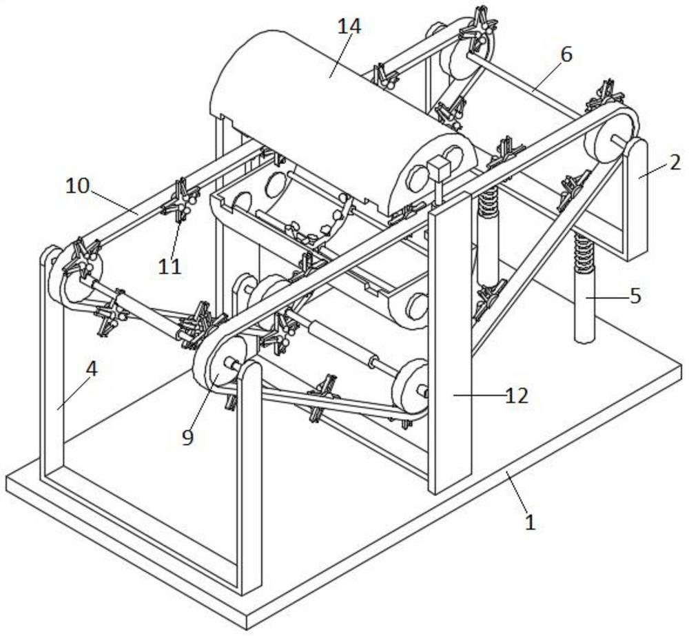
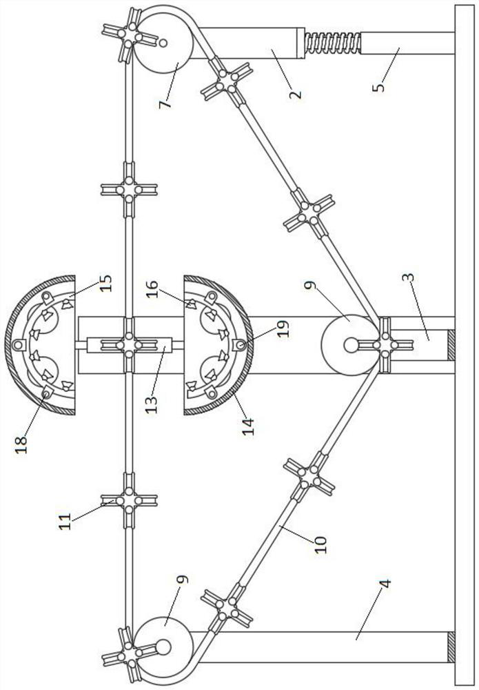
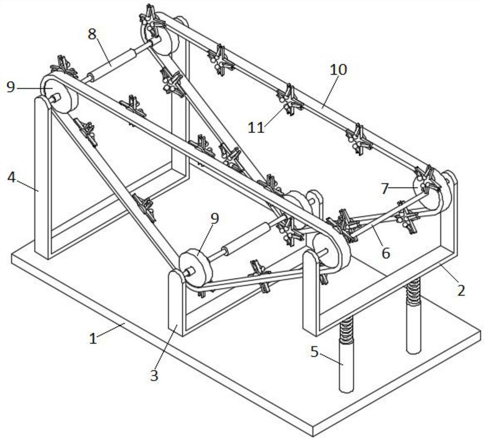
[0023] see Figure 1-5 As shown, the present invention is a spraying device for monitoring the processing of vertical rods, including a horizontally arranged substrate 1; a first U-shaped frame 2, a second U-shaped frame 3 and a first U-shaped frame 3 are arranged vertically above the substrate 1 The third U-shaped frame 4; the first U-shaped frame 2 is installed on the upper surface of the substrate 1 through a pair of elastic expansion parts 5; the elastic expans...


PUM


Abstract

The invention discloses a spraying device for monitoring vertical rod machining, and relates to the technical field of monitoring vertical rod machining. The device comprises a base plate which is horizontally arranged; a first U-shaped frame, a second U-shaped frame and a third U-shaped frame are vertically arranged above the base plate side by side; the first U-shaped frame is arranged on the upper surface of the base plate through a pair of elastic telescopic components; a driving shaft is rotationally arranged between the two ends of the upper part of the first U-shaped frame; a pair of first belt wheels are fixed on the driving shaft side by side; the second U-shaped frame and the third U-shaped frame are both fixed to the upper surface of the base plate; the two ends of the upper portion of the second U-shaped frame and the two ends of the upper portion of the third U-shaped frame are each fixedly provided with a bearing rod; and the bearing rods are coaxially sleeved with supporting sleeves. The spraying device is simple and reasonable in structural design and convenient to use, the paint spraying efficiency and effect of a monitoring vertical rod are effectively improved, and the spraying device has higher market application value.

Description

technical field [0001] The invention belongs to the technical field of monitoring pole processing, in particular to a spraying device for monitoring pole processing. Background technique [0002] At present, the surface of most monitoring poles on the market is usually sprayed with color to meet the aesthetic requirements of the racket frame, so it is necessary to spray paint on the surface of the monitoring pole. The traditional painting equipment is to spray paint through the fixed spray gun bracket. Due to the limited spray range of the fixed spray gun bracket, when a large-scale spray is required, it is necessary to manually move the position of the spray gun up and down to spray the entire monitoring pole, and manual adjustment is prone to spraying Issues with inaccurate ranges, resulting in inconsistent coatings on monitoring poles. In addition, traditional painting equipment can only spray part of the surface of the monitoring pole. When another part of the surface n...

Claims


Application Information

Patent Timeline
Patent Type & Authority Applications(China)
IPC IPC(8): B05B16/00B05B13/02
CPCB05B13/0221B05B16/95
Inventor 吴纯虎
Owner 安徽星露科技发展有限公司
Learn More