
Voice coil vibration and sound player two-in-one motor with high vibration strength

A technology of vibration intensity and player, which is applied in the direction of electrical components, electromechanical devices, electric components, etc., can solve the problems of low efficiency and affecting the vibration performance of motors, and achieve the effect of small interference and large vibration

Pending Publication Date: 2021-01-26
ONCE TOP MOTOR MFG
View PDF0 Cites 0 Cited by
  • Summary
  • Abstract
  • Description
  • Claims
  • Application Information

AI Technical Summary

Problems solved by technology

[0003] In the prior art, the structural layout characteristics of the voice coil motor with the current structure in the industry are as follows: the mover of the motor is the design center magnet, and the magnetic pole direction of the magnet is consistent with the vibration direction; the outer coil is a spiral tube type, and after the coil is energized, The direction of the excited magnetic field is the axial direction of the helical tube. The more turns of the coil and the thicker the wall thickness of the hollow coil, the greater the forced vibration dynamic force can be generated, and the vibration intensity of the motor can be improved; and the motor has no vibration on the outside of the magnet. Design magnetically permeable components to form a closed magnetic circuit for the internal magnetic field of the motor; from this structure, the efficiency is relatively low; and the motor is greatly affected by the interference of the external magnetic field, or the installation positions of the two voice coil motors are similar or installed Different postures seriously affect the vibration performance of the motor

Method used


Image

  • Voice coil vibration and sound player two-in-one motor with high vibration strength
  • Voice coil vibration and sound player two-in-one motor with high vibration strength
  • Voice coil vibration and sound player two-in-one motor with high vibration strength

Examples


Embodiment Construction

[0030] In order to make the object, technical solution and advantages of the present invention clearer, the present invention will be further described in detail below in conjunction with the accompanying drawings and embodiments. It should be understood that the specific embodiments described here are only used to explain the present invention, not to limit the present invention.

[0031] In the description of the present invention, it should be noted that the terms "center", "upper", "lower", "left", "right", "vertical", "horizontal", "inner", "outer" etc. The indicated orientation or positional relationship is based on the orientation or positional relationship shown in the drawings, and is only for the convenience of describing the present invention and simplifying the description, rather than indicating or implying that the referred device or element must have a specific orientation, or in a specific orientation. construction and operation, therefore, should not be constr...


PUM


Abstract

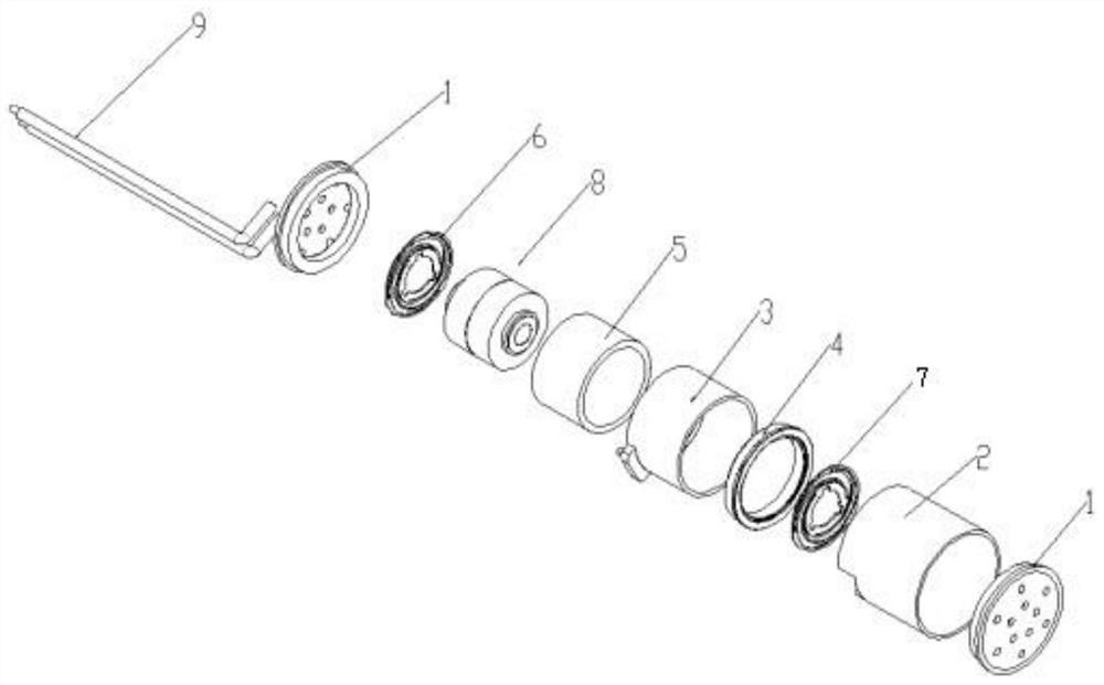
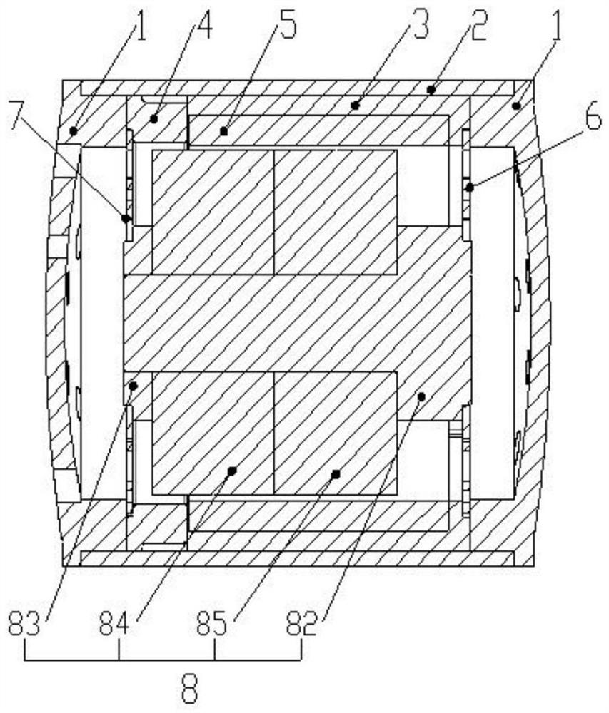
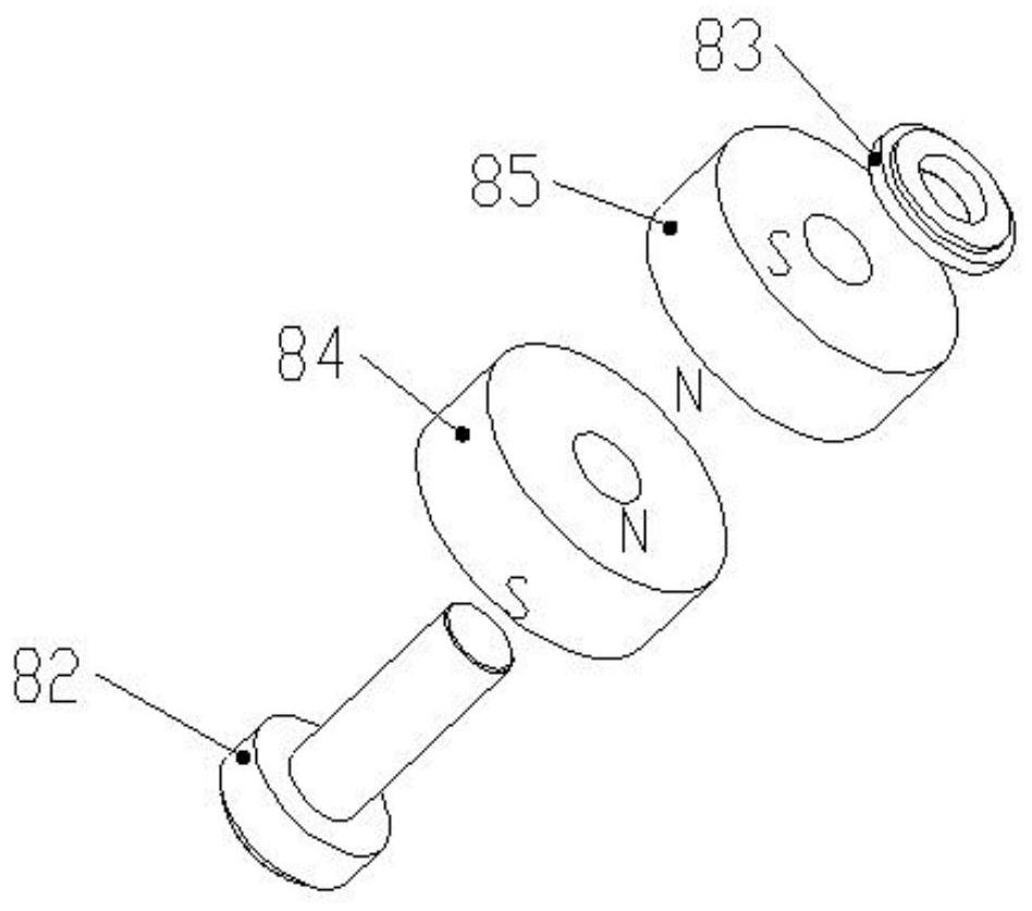
The invention relates to the technical field of motors, and discloses a voice coil vibration and sound player two-in-one motor with high vibration strength. The motor comprises a motor shell; two motor end covers which are sequentially mounted at the two ends of the motor shell and used for sealing openings in the two ends of the motor shell; a coil fixing frame which is embedded in the motor shell; a motor coil which is used for generating an excitation magnetic field after being electrified; a vibration assembly which is embedded in the motor coil; a fixed bracket which is propped against the coil fixing frame and the motor coil; a first elastic sheet which is connected with the coil fixing frame and is used for motor vibration; a second elastic sheet which is fixedly connected with thefixed bracket and is used for vibrating the motor; and a wire which penetrates through one end of the motor end cover, is electrically connected with the motor coil and is used for being electricallyconnected with an external power supply and inputting the power supply. The motor disclosed by the invention is high in electromagnetic efficiency and large in vibration quantity, and the interferenceinfluence degree between the motors and between the motors and an external magnetic field is very small.

Description

technical field [0001] The invention relates to the technical field of electric motors, in particular to a high-vibration strength voice coil vibration and audio player two-in-one electric motor. Background technique [0002] Used in the central control operation panel of self-driving cars, smart home touch panels and massage audio vibrators, etc., motors with vibration or music playback functions are required to realize the touch sensing response feedback function; in the head or eye massage category Products that require high vibration intensity or music effect motors. There are usually two solutions for motors that meet this function: one is to choose a rotary motor with an eccentric swing head, or to use a voice coil motor structure; the rotary motor is used because the motor has a trial life and response delay. The time and vibration stress is relatively low, the efficiency is low, and there will be no shortage of audio player functions; furthermore, a voice coil struc...

Claims


Application Information

Patent Timeline
IPC IPC(8): H02K33/18H02K33/02H02K5/22H02K5/20
CPCH02K5/20H02K5/225H02K33/02H02K33/18
Inventor 翁孟坤周志鹏
Owner ONCE TOP MOTOR MFG
Learn More