Photovoltaic bracket for photovoltaic power station, and mounting method thereof

A photovoltaic support, photovoltaic power station technology, applied in the support structure of photovoltaic modules, photovoltaic power generation, fixed base/support of solar collectors, etc., can solve problems such as unfavorable installation of photovoltaic supports, and achieve convenient installation and labor-saving use. , Improve the effect of support

Active Publication Date: 2021-01-22
江阴市源硕金属科技有限公司
View PDF12 Cites 3 Cited by
  • Summary
  • Abstract
  • Description
  • Claims
  • Application Information

AI Technical Summary

Problems solved by technology

[0004] The purpose of the present invention is to provide a photovoltaic support for photovoltaic power plants. By designing a new type of connector, it is convenient for the staff to install between the top beam and the support beam and the front leg and the rear leg. By designing a new type of positioning The device is matched with the new installation method of the front outrigger and the rear outrigger, which is convenient for the staff to install the front outrigger and the rear outrigger. At the same time, the positioning piece is designed to facilitate the staff to install the support beam at the position without the connecting piece. The installation solves the problem that the existing photovoltaic support is not conducive to installation

Method used


Image

  • Photovoltaic bracket for photovoltaic power station, and mounting method thereof
  • Photovoltaic bracket for photovoltaic power station, and mounting method thereof
  • Photovoltaic bracket for photovoltaic power station, and mounting method thereof

Examples


Embodiment Construction

[0045] The following will clearly and completely describe the technical solutions in the embodiments of the present invention with reference to the accompanying drawings in the embodiments of the present invention. Obviously, the described embodiments are only some, not all, embodiments of the present invention. Based on the embodiments of the present invention, all other embodiments obtained by persons of ordinary skill in the art without creative efforts fall within the protection scope of the present invention.

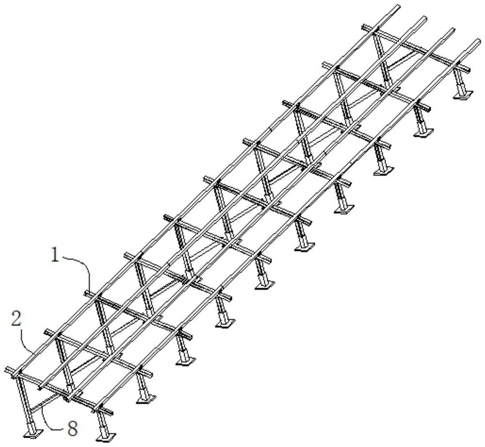
[0046] see Figure 1-3 As shown, the present invention is a photovoltaic support for a photovoltaic power station, including several support frames 1 arranged side by side, four rows of support beams 2 are fixed side by side on the top of several support frames 1, and the support beams 2 and support frames 1 are perpendicular to each other, supporting Frame 1 includes front outrigger 3, rear outrigger 4 and top beam 5;

[0047]One end of the front outrigger 3 and ...


PUM


Abstract

The invention discloses a photovoltaic bracket for a photovoltaic power station, and a mounting method thereof, and relates to the technical field of photovoltaic brackets. The photovoltaic bracket comprises a plurality of supporting frames arranged side by side, wherein four rows of supporting beams are fixed to the tops of the supporting frames side by side, the supporting beams are perpendicular to the supporting frames, each supporting frame comprises a front supporting leg, a rear supporting leg and a top beam, embedded pieces are fixed to one ends of the front supporting legs and the rear supporting legs, and the front supporting legs and the rear supporting legs are fixed to the ground in parallel through the embedded pieces and concrete. By designing the novel connecting pieces, aworker can conveniently install the top beam, the supporting beams, the front supporting legs and the rear supporting legs, by designing the novel positioning devices and matching with the novel installation modes of the front supporting legs and the rear supporting legs, the worker can conveniently install the front supporting legs and the rear supporting legs, and by designing the positioning pieces, the worker can conveniently install the supporting beam at the position without the connecting piece, and the problem that an existing photovoltaic bracket is not convenient to install is solved.

Description

technical field [0001] The invention belongs to the technical field of photovoltaic supports, and in particular relates to a photovoltaic support for a photovoltaic power station and an installation method thereof. Background technique [0002] For the photovoltaic brackets used in photovoltaic power stations, the inclined brackets are divided into multiple rows and installed side by side in an open area, and the photovoltaic modules are linearly installed on the photovoltaic brackets. In order to save costs, the ground of the photovoltaic power generation area of ​​the existing photovoltaic power stations is mostly Sand or land. [0003] Due to the unevenness of the ground in the installation area, a large number of measurements and positioning are required for the staff during installation, which affects the installation efficiency of the staff. At the same time, manual assistance is required to lift and limit the position of the beam body during installation, which is not...

Claims


Application Information

Patent Timeline
Patent Type & Authority Applications(China)
IPC IPC(8): H02S20/00F24S25/636F24S25/67
CPCF24S25/636F24S25/67H02S20/00Y02E10/47Y02E10/50
Inventor 韩宗育程凯迪蒋兰兰
Owner 江阴市源硕金属科技有限公司
Why Eureka
Try Eureka