
Speed changing device

A speed change device and turntable technology, which is applied in the field of speed change transmission, can solve the problems of large size of the speed change device, affect the service life, and be prone to failure, etc., and achieve the effects of large change range, extended life, and strong applicability

Inactive Publication Date: 2021-01-22
汪家发
View PDF0 Cites 0 Cited by
  • Summary
  • Abstract
  • Description
  • Claims
  • Application Information

AI Technical Summary

Problems solved by technology

[0002] Variable speed transmission is a commonly used form of function transformation. Most of the existing transmission devices are large in size, heavy in weight, and high in cost. They are prone to failure after working for a long time, which affects their service life.

Method used


Image

  • Speed changing device
  • Speed changing device
  • Speed changing device

Examples


Embodiment 1

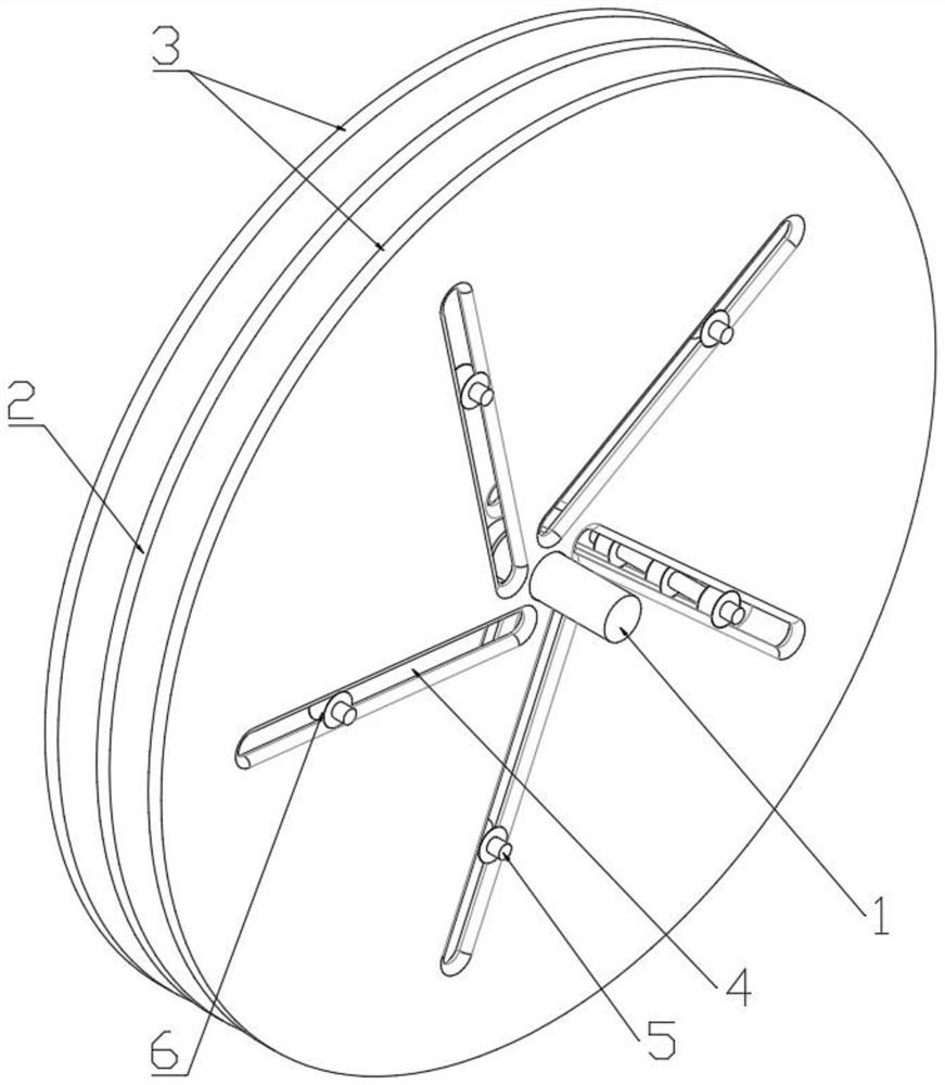
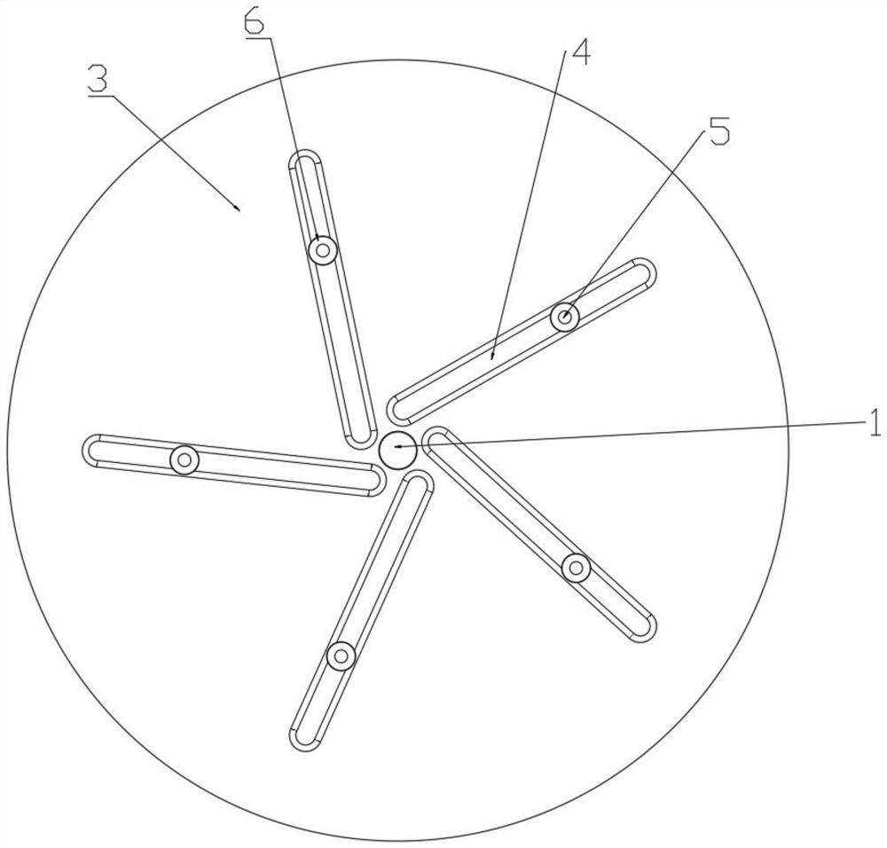
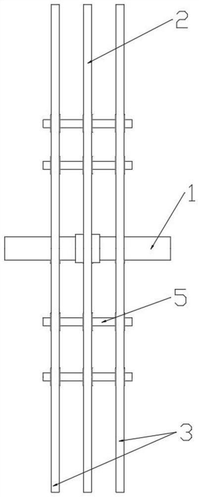
[0014] Embodiment 1, in conjunction with attached Figure 1-3 , a speed change device, comprising a rotating main shaft 1, a fixed turntable 2 fixedly connected to the rotating main shaft 1, a driven turntable 3 symmetrically arranged on both sides of the fixed turntable 2, and the driven turntable 3 is rotatably connected to the rotating main shaft 1; The fixed turntable 2 and the driven turntable 3 are provided with strip chutes 4 that cooperate with each other. A plurality of bar-shaped chutes 4 on the driven turntable 3 are evenly distributed along the circumference, and a plurality of bar-shaped chutes 4 are evenly distributed along the circumference; the bar-shaped chute 4 is provided with a slide bar 5, and the The direction of extension of the slide bar 5 is perpendicular to the surface where the fixed turntable 2 is located. The slide bar 5 is rotatably connected with a roller 6 cooperating with the strip chute 4 . The roller 6 can only slide and roll relative to the ...

Embodiment 2

[0017] Embodiment 2, in conjunction with attached Figure 4 , comprising a rotating main shaft 1, a fixed turntable 2 fixedly connected to the rotating main shaft 1, a driven turntable 3 symmetrically arranged on both sides of the fixed turntable 2, and the driven turntable 3 is rotationally connected with the rotating main shaft 1; the fixed turntable 2 1. The driven turntable 3 is provided with bar chutes 4 that cooperate with each other, and the number of bar chutes 4 on the fixed turntable 2 and the driven turntable 3 is provided with a plurality, and the plurality of bar chutes on the fixed turntable 2 Shaped chute 4 is evenly distributed along the circumference, and a plurality of bar-shaped chutes 4 on the driven turntable 3 are evenly distributed along the circumference; the bar-shaped chute 4 is provided with a slide bar 5, and the extension direction of the slide bar 5 Vertical to the surface where the fixed turntable 2 is located, the slide bar 5 is rotatably connec...


PUM


Abstract

The invention discloses a speed changing device which comprises a rotating main shaft, a fixed rotating disc fixedly connected to the rotating main shaft and driven rotating discs symmetrically arranged at two sides of the fixed rotating disc, the driven rotating discs are rotatably connected with the rotating main shaft, the fixed rotating disc and the driven rotating disc are provided with strip-shaped chutes matched with each other, the number of the strip-shaped chutes in the fixed rotating disc and the driven rotating disc is multiple, the multiple strip-shaped chutes in the fixed rotating disc are uniformly distributed along the circumference, the multiple strip-shaped chutes in the driven rotating disc are uniformly distributed along the circumference, a sliding rod is arranged in each strip-shaped chute, the extending direction of the sliding rod is perpendicular to the plane where the fixed rotating disc is located, the sliding rod is rotatably connected with a roller matchedwith the strip-shaped chute, and the roller can only slide and roll relative to the strip-shaped chute. According to the device, a new speed changing mode is provided the characteristics of light weight, small size, low manufacturing cost and large transmission ratio change range are achieved, the condition that an engine always does work in a rated power range can be guaranteed, the service lifetime of the engine is prolonged, and the applicability is high.

Description

technical field [0001] The present invention relates to the technical field of speed change transmission, and specifically refers to a speed change device. Background technique [0002] Variable speed transmission is a commonly used form of function transformation. Most of the existing transmission devices are large in size, heavy in weight, high in cost, and prone to failure after long-term work, which affects their service life. Contents of the invention [0003] The technical problem to be solved by the present invention is to overcome the above technical defects and provide a transmission device. [0004] In order to solve the above technical problems, the technical solution provided by the present invention is a transmission device: comprising a rotating main shaft, a fixed turntable fixedly connected to the rotating main shaft, and driven turntables arranged symmetrically on both sides of the fixed turntable. The rotating main shaft is rotatably connected; the fixed...

Claims


Application Information

Patent Timeline
Patent Type & Authority Applications(China)
IPC IPC(8): F16H35/18H02K7/14
CPCF16H35/18H02K7/14Y02T10/64
Inventor 汪家发
Owner 汪家发
Learn More