
Terminal shell Mic hole mold structure

A terminal shell and mold technology, applied in the coating and other directions, can solve problems such as tip breakage, and achieve the effect of reducing costs and simplifying the replacement process.

Active Publication Date: 2021-01-22
HUAQIN TECH CO LTD
View PDF5 Cites 0 Cited by
  • Summary
  • Abstract
  • Description
  • Claims
  • Application Information

AI Technical Summary

Problems solved by technology

[0004] The purpose of the embodiments of the present invention is to provide a terminal shell Mic hole mold structure, and at the same time solve the problems of edging and fracture in the related art

Method used


Image

  • Terminal shell Mic hole mold structure
  • Terminal shell Mic hole mold structure
  • Terminal shell Mic hole mold structure

Examples


Embodiment Construction

[0020] In order to make the purpose, technical solutions and advantages of the embodiments of the present invention clearer, the embodiments of the present invention will be described in detail below with reference to the accompanying drawings. However, those skilled in the art can understand that in each embodiment of the present invention, many technical details are provided for readers to better understand the present application. However, even without these technical details and various changes and modifications based on the following embodiments, the technical solutions claimed in this application can also be realized. The division of the following embodiments is for the convenience of description, and should not constitute any limitation to the specific implementation of the present invention, and the various embodiments can be combined and referred to each other on the premise of no contradiction.

[0021] The serial numbers assigned to the components in this document, ...


PUM

PropertyMeasurementUnit
Rockwell hardnessaaaaaaaaaa

Abstract

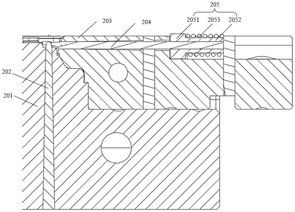
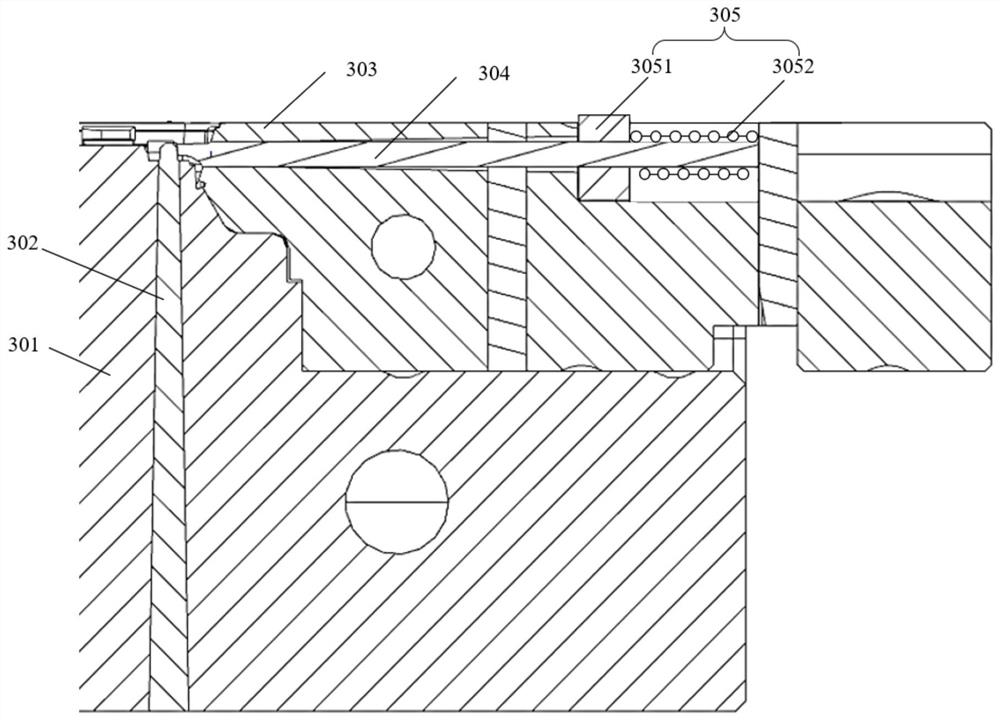
The embodiment of the invention relates to the technical field of terminals, and discloses a terminal shell Mic hole mold structure. The terminal shell Mic hole mold structure comprises a rear mold, arear mold insert, a slide, a slide insert and an elastic assembly, wherein the rear mold insert is fixed in the rear mold, and the slide insert is movably arranged in a groove of the slide, so that when the rear mold matches with the slide, the slide insert realizes that the first end of the slide insert is propped against the first end of the rear mold insert under the action of the elastic force of the elastic assembly, therefore, the first end of the slide insert and the first end of the rear mold insert cannot be broken due to transition fit, the problem of burrs due to clearance fit is solved, and the problems of the burrs and breakage in related technologies are solved at the same time.

Description

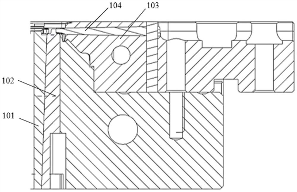
technical field [0001] Embodiments of the present invention relate to the technical field of terminals, and in particular to a mold structure for a Mic hole in a terminal housing. Background technique [0002] At present, with the popularization of terminal products, the performance of a microphone (Mic, Microphone) hole on the casing has gradually become the focus of attention of users. Such as figure 1 As shown, it is a schematic diagram of the surface structure of the Mic hole mold structure section in the related art, including: a rear mold 101, a rear mold insert 102, a row position 103, and a row position insert 104; wherein, the row position insert 104 is fixed in the row position 103, the back mold insert 102 is fixed on the back mold 101, the first end of the back mold insert 102 exposes the back mold 101, the first end of the row position insert 104 exposes the row position 103, and the back mold insert 102 the first end One end is matched with the first end of t...

Claims


Application Information

Patent Timeline
Patent Type & Authority Applications(China)
IPC IPC(8): B29C45/33B29C45/14B29C33/30B29C45/26
CPCB29C45/33B29C45/14B29C45/2675Y02E60/10
Inventor 胡明慧李小春何年锋
Owner HUAQIN TECH CO LTD
Learn More