Surgical retractor forceps

A retractor forceps and surgery technology, applied in the field of surgical retractor forceps, can solve the problems of complex operation, lack of flexibility, weak versatility, etc., and achieve the effects of increasing the force bearing area and improving the expansion effect.

Pending Publication Date: 2021-01-22
SHANGHAI FIRST PEOPLES HOSPITAL
View PDF2 Cites 0 Cited by
  • Summary
  • Abstract
  • Description
  • Claims
  • Application Information

AI Technical Summary

Problems solved by technology

Its structure is simple, and it can pull large and small wounds when performing surgery on patients, fully exposing the surgical field of view. It solves the problem of increasing the pulling area of ​​a single retractor, but does not solve the above-mentioned problems of complicated operation and inflexible use
[0004] Chinese patent application CN210228220U discloses a surgical retractor, which includes a retractor body; the retractor body includes a working end and a handle end; the working end is symmetrically provided with two rows of pulling claws; Adjust the distance between the two rows of retracting claws; each row of retracting claws includes a plurality of teeth arranged side by side, and the length of the teeth is from one side of the retracting claws to the other. The side first increases and then decreases, that is, the extension ends of each tooth can be connected to form a certain arc; while in the prior art, the lengths of each tooth are equal, and the extension ends of each tooth are connected to form a straight line; it is more in line with the human spine The physiological curvature of the lumbar segment can effectively expose the surgical field of view. The above-mentioned patent avoids the physiological curvature of the lumbar segment of the spine by setting the length of the teeth to prevent the expansion of the surgical field of view; but its expansion is affected by the size of the instrument , extremely inflexible and weak in versatility

Method used


Image

  • Surgical retractor forceps
  • Surgical retractor forceps
  • Surgical retractor forceps

Examples


Embodiment Construction

[0029] The present invention will be further described below in combination with specific embodiments. It should be understood that these examples are only used to illustrate the present invention and are not intended to limit the scope of the present invention. In addition, it should be understood that after reading the contents of the present invention, those skilled in the art can make various changes or modifications to the present invention, and these equivalent forms also fall within the scope defined by the appended claims of the present application.

[0030] The reference signs and components involved in the accompanying drawings are as follows:

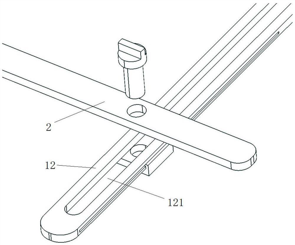
[0031] 1. Clamp body 2. Pull rod 3. Mounting part

[0032] 11. Operation lever 12. Guide lever 13. Connecting part

[0033] 14. Stopping mechanism 21. Clamping device 22. Regulating device

[0034] 23. Balance device 31. Fixed end 32. Contact end

[0035] 121. Guide rail 311. Card slot

[0036] Please see attached figur...


PUM


Abstract

The invention relates to a pair of surgical retractor forceps. The surgical retractor forceps comprise forceps bodies, retraction rods and installation parts; each installation part is detachably connected with the corresponding retraction rod; each retraction rod is movably connected with the corresponding forceps body; the installation parts are used for fitting a retracted part; each forceps body includes an operating rod and a guide rod; each guide rod is provided with a guide rail; each retraction rod is slidably connected with the corresponding guide rail; each installation part includesa fixed end and a contact end; each contact end can be a combination of a plurality of retractors; the forceps bodies, the retraction rods and the installation parts are each arranged in pairs; the paired forceps bodies are movably hinged; and the distance between the paired installation parts can be adjusted through the operating rods. The surgical retractor forceps disclosed by the invention are flexible to operate, and can different retraction schemes can be replaced according to the surgical needs.

Description

technical field [0001] The invention relates to the technical field of medical instruments, in particular to a surgical hook forceps. Background technique [0002] Clinically, the smaller the surgical scar, the better the postoperative wound recovery and the more beautiful, so all open surgery nowadays strives to reduce the incision, so as to achieve the above purpose. Because the skin has a certain degree of elasticity and toughness, after opening to a certain extent, various pull hooks can be used to temporarily expand the opening without enlarging the incision. However, for retractors, this operation requires at least two hands, which is very laborious for assistants, and because of the limited open surgical field of view, retractor assistants cannot accurately control the position, and even if the main knife is adjusted If the position is changed, the hook assistant may still have a direction deviation due to uneven force and limited physical strength. For people with l...

Claims


Application Information

Patent Timeline
Patent Type & Authority Applications(China)
IPC IPC(8): A61B17/02A61B17/28
CPCA61B17/02A61B17/2812
Inventor 郑重郑军华刘志宏王翔李明清伍科姚智显周文洁郑心怡刘语瞳穆星宇孙丰赵伟光
Owner SHANGHAI FIRST PEOPLES HOSPITAL
Why Eureka
Try Eureka