


Quick Research
Generate reliable direction feasibility study reports for your R&D in just a few steps.

Technical Q&A
Discover and master advanced knowledge NOW. Basics, ideas, possibilities, all at once.

Find Solutions
As an expert in R&D theories, this can generate solutions to your technical problems instantly.

Evaluate Feasibility
Analyze your overall solution with one click, know your potential R&D risks in advance.

Monitor Landscape
Get weekly tech updates, stay abreast of the latest tech innovations and key insights.
Minitype teflon tape winding device for hydraulic engineering
A winding device and raw material tape technology, applied in the direction of threaded connection, pipe/pipe joint/pipe fitting, passing components, etc., can solve the problems of troublesome operation and low work efficiency, achieve convenient operation, high work efficiency, and improve winding efficiency Effect
- Summary
- Abstract
- Description
- Claims
- Application Information
AI Technical Summary
Problems solved by technology
Method used
Image

Examples
Embodiment 1
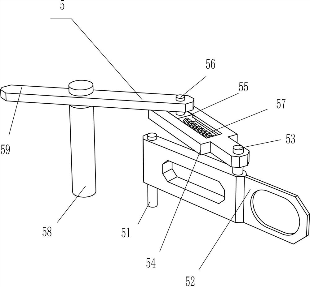
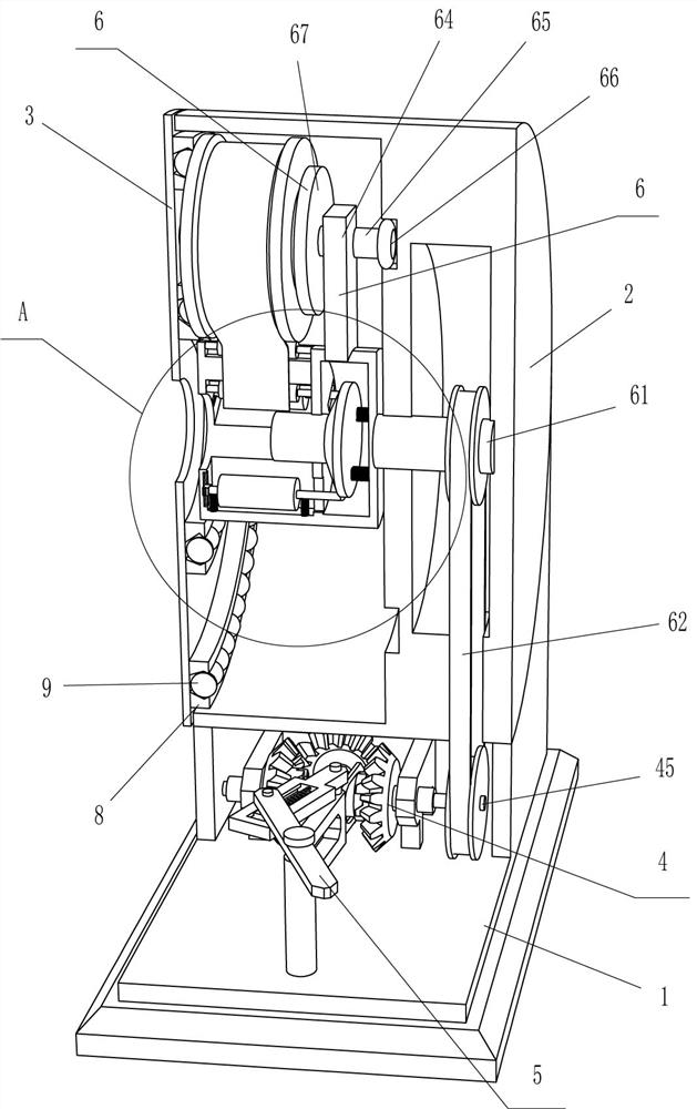
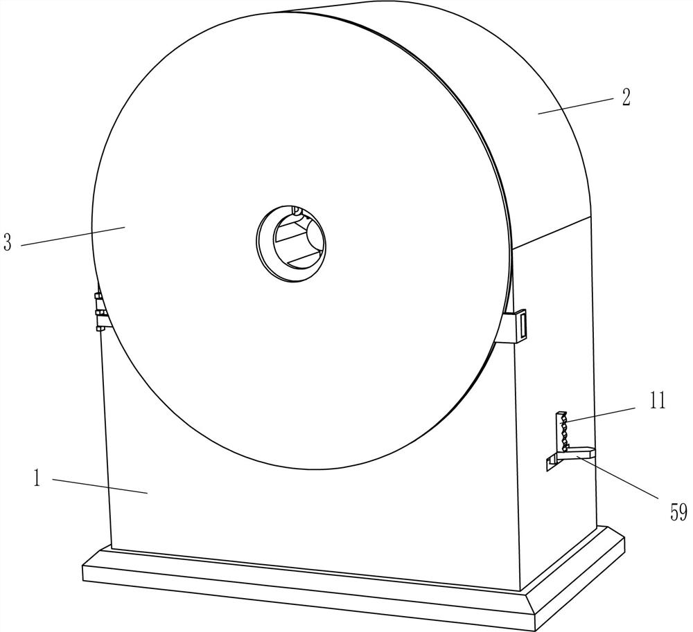
[0027] A small-sized raw material belt winding device for hydraulic engineering, such as Figure 1-Figure 5 As shown, it includes a square shell 1, a cylindrical shell 2, a front cover 3, a driving device 4, a reversing device 5, and a discharge device 6. The top of the square shell 1 is fixedly connected to the cylindrical shell 2, and the left side The upper part is hinged with a front cover 3, and the front cover 3 is in contact with the opening of the cylindrical shell 2. The inner bottom of the square shell 1 is provided with a drive device 4, and the square shell 1 is provided with a reversing device 5. The reversing device 5 and the drive device 4 Contact fit, a discharge device 6 is arranged inside the cylindrical shell 2, and the discharge device 6 is fixedly connected with the driving device 4.
[0028]The driving device 4 includes a motor 41, a first rotating shaft 42, a stand 43, a first bevel gear 44, a protruding shaft 45, a first drum 46, a second bevel gear 47,...
Embodiment 2
[0036] On the basis of Example 1, such as figure 2 , image 3 with Figure 6 As shown, also include pressing device 7, and pressing device 7 comprises extruding block 71, second back-moving spring 72, contact bar 73, second slide block 74, pressing material column 75 and the 3rd back-moving spring 76, rotates The center of the rear side of the column 63 is slidingly provided with an extruding block 71, and the rear side of the extruding block 71 is fixedly connected with three second return springs 72 at even intervals, and the tail ends of the three second return springs 72 are fixedly connected with the interior of the rotating column 63 , the front side of the rotating column 63 is slidingly provided with three second sliders 74, the rear side of the second slider 74 is fixedly connected with a contact rod 73, the contact rod 73 is in contact with the extrusion block 71, and the front side of the contact rod 73 is circumferentially A pressing column 75 is connected in a ...
Embodiment 3
[0039] On the basis of embodiment 1 and embodiment 2, such as figure 1 , figure 2 , image 3 with Figure 7 As shown, it also includes a groove ring 8 and a ball 9. Two groove rings 8 are affixed to the rear side of the front cover 3 in the circumferential direction, and the evenly spaced rotation in the groove ring 8 is provided with balls 9 .
[0040] It also includes a lock block 10, a dial block 11 and a fourth return spring 12. The inside of the right side of the square housing 1 is slidably provided with a lock block 10. The lock block 10 contacts and cooperates with the long plate 59, and the upper part of the right side of the lock block 10 is affixed. There is a dial block 11, and a fourth return spring 12 is affixed between the top of the lock block 10 and the inside of the right side of the square housing 1.
[0041] When the discharge column 67 drives the raw material belt to rotate, the ball 9 is in contact with the raw material belt. Due to the effect of the ...
PUM
 Abstract
Description
Claims
Application Information
 - R&D Engineer
- R&D Manager
- IP Professional
- Industry Leading Data Capabilities
- Powerful AI technology
- Patent DNA Extraction
Browse by: Latest US Patents, China's latest patents, Technical Efficacy Thesaurus, Application Domain, Technology Topic, Popular Technical Reports.
© 2024 PatSnap. All rights reserved.Legal|Privacy policy|Modern Slavery Act Transparency Statement|Sitemap|About US| Contact US: help@patsnap.com