
Power control cabinet

A technology for power control cabinets and cabinet doors, which is applied in the field of electric power, can solve the problems of improper setting position, hindering maintenance personnel from overhauling, and the lock rod assembly occupies a large space and is unsightly, and achieves reasonable and compact setting, reduced structure and occupied effect of space

Active Publication Date: 2021-01-15
山东春鹏电气有限公司
View PDF9 Cites 0 Cited by
  • Summary
  • Abstract
  • Description
  • Claims
  • Application Information

AI Technical Summary

Problems solved by technology

[0002] The power control cabinet includes the cabinet body and the cabinet door. The cabinet body and the cabinet door generally need to be locked by the lock rod assembly to prevent the cabinet door from opening automatically and causing danger. The lock rod assembly uses the plug-in cooperation of the lock pin and the lock seat to achieve locking. Yes, the operating part that controls the mating of the lock pin and the lock seat and the control part that controls the disengagement of the lock pin and the lock seat are often the same part. Because of the high requirements for linkage, the internal structure of the lock lever assembly will be very complicated. Although there is a phenomenon in the prior art that the operating part that controls the locking pin and the lock seat to be plugged and matched and the operating part that controls the locking pin and the lock seat to disengage are set as two parts, but due to the improper setting position, the entire lock rod assembly It takes up a lot of space and is not beautiful, and it will also hinder the maintenance of the maintenance personnel

Method used


Image

  • Power control cabinet
  • Power control cabinet
  • Power control cabinet

Examples


Embodiment Construction

[0024] The specific implementation manners of the present invention will be further described in detail below in conjunction with the accompanying drawings and embodiments. The following examples are used to illustrate the present invention, but should not be used to limit the scope of the present invention.

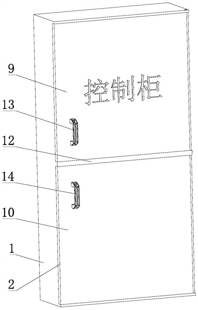
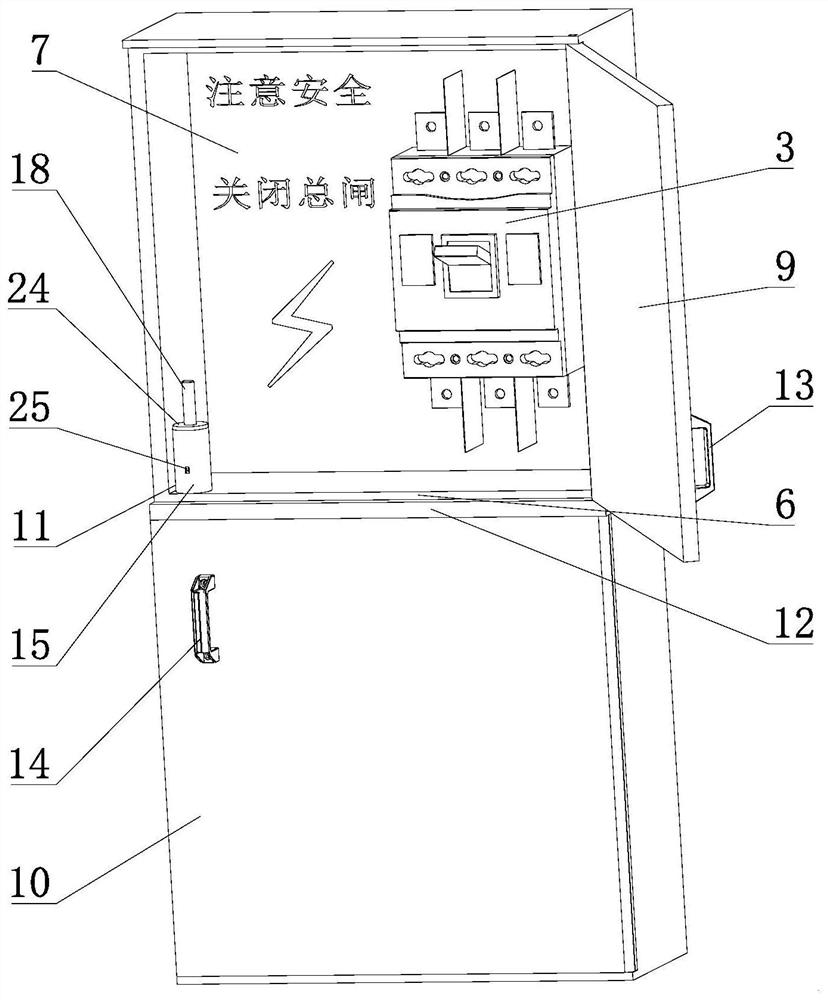
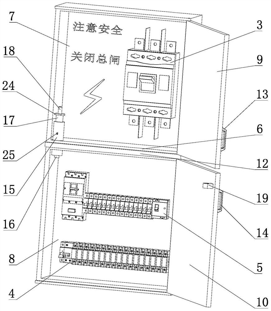
[0025] The structure of the power control cabinet of the present embodiment is as Figure 1 to Figure 7 Shown includes a cabinet 1 and a cabinet door 2, the cabinet 1 is used to place the main power switch 3, a number of circuit breakers 4 and a number of fuses 5, etc., the cabinet 1 is provided with a partition 6, and the partition 6 separates the cabinet 1. Divided into upper cabinet body 7 and lower cabinet body 8. Cabinet door 2 covers upper cabinet door 9 and lower cabinet door 10. Upper cabinet door 9 is hinged with upper cabinet body 7. Lower cabinet door 10 is hinged with lower cabinet body 8. Cooperate, the main switch 3 of the power supply is installed in the ...


PUM


Abstract

The invention discloses a power control cabinet which comprises a cabinet body and a cabinet door. The cabinet body and the cabinet door are locked through a lock rod assembly, the lock rod assembly comprises a lock shell, a lock pin, a lock pin spring, a lock rod and an unlocking rod, the lock pin, the lock pin spring, the lock rod and the unlocking rod are located in the lock shell, and the cabinet door is provided with a lock seat matched with the lock pin. The lock rod is provided with a lock cavity and an elastic clamp and an unlocking rod spring which are located in the lock cavity. Thelock pin is fixedly connected with the bottom of the lock rod, the unlocking rod and the lock rod are concentrically arranged, the unlocking rod and the lock rod are in sliding insertion fit and extend into the lock cavity to face the elastic clamp, the lock rod is provided with a lock rod handle, and the lock pin and the lock base can be connected in a matched mode by overcoming the acting forceof the lock rod spring to press the lock rod handle downwards. After the lock pin and the lock base are connected in place in a matched mode, the elastic clamp is connected with the lock hole of the lock shell in a matched mode, the acting force of the unlocking rod spring is overcome, the unlocking rod is pressed downwards to enable the elastic clamp to be separated from the lock hole of the lockshell, and the lock pin is separated from the lock base and reset under the action of the lock pin spring. The lock rod assembly is arranged very reasonably and compactly, the structure and occupiedspace of the lock rod assembly are effectively reduced, and therefore overhauling of overhauling personnel cannot be hindered.

Description

technical field [0001] The invention relates to the field of electric power technology, in particular to an electric power control cabinet. Background technique [0002] The power control cabinet includes the cabinet body and the cabinet door. The cabinet body and the cabinet door generally need to be locked by the lock rod assembly to prevent the cabinet door from opening automatically and causing danger. The lock rod assembly uses the plug-in cooperation of the lock pin and the lock seat to achieve locking. Yes, the operating part that controls the mating of the lock pin and the lock seat and the control part that controls the disengagement of the lock pin and the lock seat are often the same part. Because of the high requirements for linkage, the internal structure of the lock lever assembly will be very complicated. Although there is a phenomenon in the prior art that the operating part that controls the locking pin and the lock seat to be plugged and matched and the ope...

Claims


Application Information

Patent Timeline
Patent Type & Authority Applications(China)
IPC IPC(8): H02B1/30H02B1/32H02B1/38H02B1/04E05C1/08
CPCH02B1/306H02B1/32H02B1/38H02B1/04E05C1/08
Inventor 李亮李潇
Owner 山东春鹏电气有限公司
Learn More