Main rolling core roller system, ring rolling mill and ring rolling mill radial main rolling core roller angle adjusting method
A technology of ring rolling machine and core roll, which is applied in the direction of rolling, metal rolling, metal rolling, etc., can solve the problems of time-consuming, laborious, multi-processing, special-shaped ring forgings that do not meet the design standards, etc., to achieve accurate rolling, reduce The effect of the amount of processing
- Summary
- Abstract
- Description
- Claims
- Application Information
AI Technical Summary
Problems solved by technology
Method used
Image
Examples
Embodiment 1
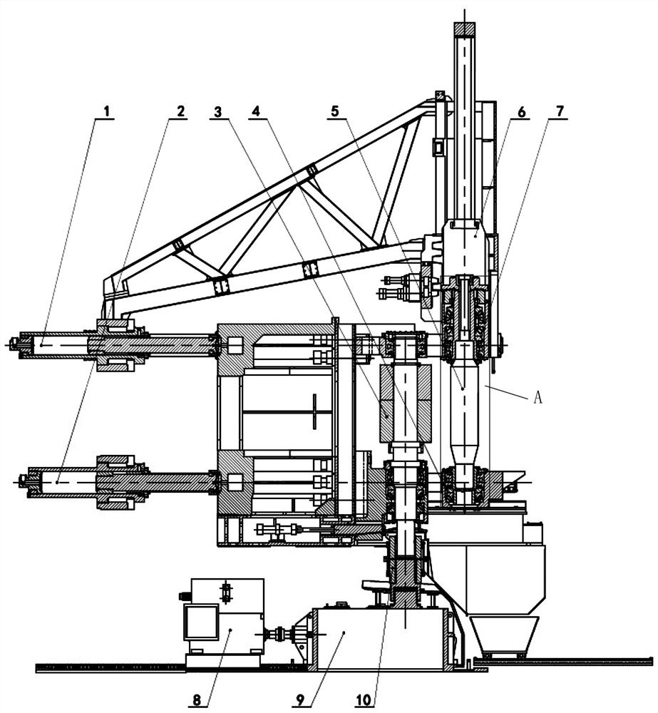
[0034] Please refer to figure 1 , which shows a schematic diagram of the overall structure of a main mandrel system provided by an embodiment of the present invention, the main mandrel system includes:
[0035] Main rolling core roll 5, one end of the main rolling core roll 5 is connected with the first main rolling core roll slider 7 through the first bearing part, and the other end of the main rolling core roll 5 is connected with the second main rolling core roll through the second bearing part The core roller slider 4 is connected;
[0036] Bearing seat guiding device, the bearing seat guiding device is respectively connected with the first main rolling core roller slider 7 and the second main rolling core roller sliding block 4, and the bearing seat guiding device is used for guiding the main rolling core roller The inclination of the mandrel roll 5 is guided, and bears the radial force and the axial force at both ends of the main mandrel roll 5;
[0037] The main rolli...
Embodiment 2
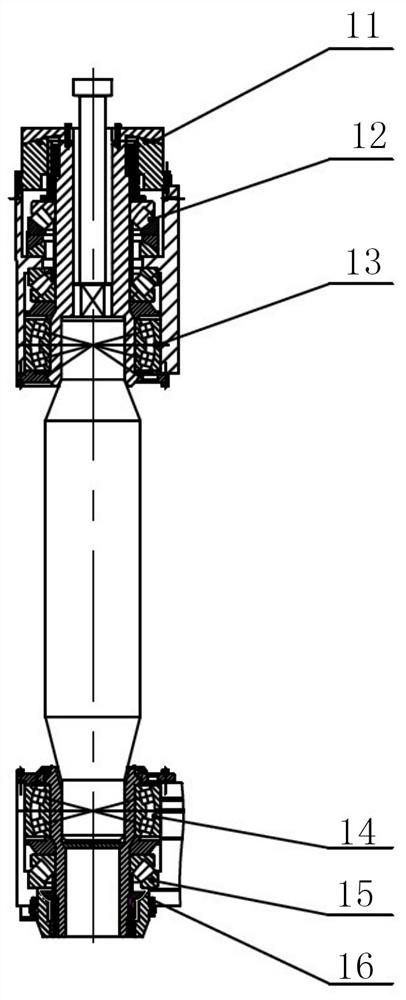
[0044] In one example, another embodiment of the main mandrel system of the present invention is as figure 2As shown, the bearing block guide device includes a first spherical guide rail 11 and a second spherical guide rail 16 oppositely arranged, and the main core roll is located between the first spherical guide rail and the second spherical guide rail, and the The first main core roll slider 7 is in sliding fit with the first spherical guide rail 11 , and the second main core roll slider 4 is in sliding fit with the second spherical guide rail 16 .
[0045] In the above embodiment, the working surface of the first spherical guide rail 11 is slidably matched with one side of the first main core roll slider 7, and the working surface of the second spherical guide rail 16 is matched with one side of the second main core roll slider 4. Slip fit.
[0046] The opening of the first spherical guide rail 11 is opposite to the opening of the second spherical guide rail 16 .
[004...
Embodiment 3
[0049] In an example, please refer to figure 1 , another embodiment of the main core roll system of the present invention, the first independent driving end 1 is a first linear transmission device, the transmission direction of the first linear transmission device is the same as that of the main core roll The axis of 5 is vertical;
[0050] The second independent driving end 2 is a second linear transmission device, and the transmission direction of the second linear transmission device is perpendicular to the axial direction of the main core roll 5 .
[0051] In the above-mentioned embodiment, the first linear transmission device and the second linear transmission device are arranged perpendicular to the axial direction of the main core roll 5, which can improve the performance of the first linear transmission device and the second linear transmission device in driving the main core roll 5. Approaching the stability of rolling main roll 3.
PUM
 Abstract
Description
Claims
Application Information
 - Generate Ideas
- Intellectual Property
- Life Sciences
- Materials
- Tech Scout
- Unparalleled Data Quality
- Higher Quality Content
- 60% Fewer Hallucinations
Browse by: Latest US Patents, China's latest patents, Technical Efficacy Thesaurus, Application Domain, Technology Topic, Popular Technical Reports.
© 2025 PatSnap. All rights reserved.Legal|Privacy policy|Modern Slavery Act Transparency Statement|Sitemap|About US| Contact US: help@patsnap.com


