
Spraying system and agricultural plant protection machine

A spraying system and plant protection machine technology, applied in the field of agricultural plant protection spraying, can solve the problems of affecting spraying efficiency, inconvenient operation, speed of spraying system maintenance or replacement affecting efficiency, etc., to achieve the effect of ensuring spraying efficiency and convenient operation

Pending Publication Date: 2021-01-12
SZ DJI TECH CO LTD
View PDF6 Cites 0 Cited by
  • Summary
  • Abstract
  • Description
  • Claims
  • Application Information

AI Technical Summary

Problems solved by technology

In addition to the spraying efficiency during the spraying process, once a failure occurs during the spraying process, the speed of maintenance or replacement of the spraying system will also affect the efficiency, delaying the precious time of busy farming, and in serious cases, the best time for spraying may be missed, resulting in irreparable economic loss
[0003] The plant protection drone spraying system in the prior art is not easy to disassemble. Usually, when working in the field, the spraying system occasionally breaks down, and it is very inconvenient to maintain. The pump set of the spraying system is usually composed of multiple water pumps, and multiple water pumps form a unit. Fixed pump set, the pump set is installed on the body as a whole
[0004] It is inconvenient to disassemble between multiple water pumps, so that once one of the water pumps fails, the entire pump set needs to be removed from the body, which is inconvenient to operate due to the heavy weight of the entire pump set, and, All taken off, the sprinkler system will only work after the current faulty water pump failure is resolved, which will seriously affect the spraying efficiency

Method used


Image

  • Spraying system and agricultural plant protection machine
  • Spraying system and agricultural plant protection machine
  • Spraying system and agricultural plant protection machine

Examples


Embodiment 1

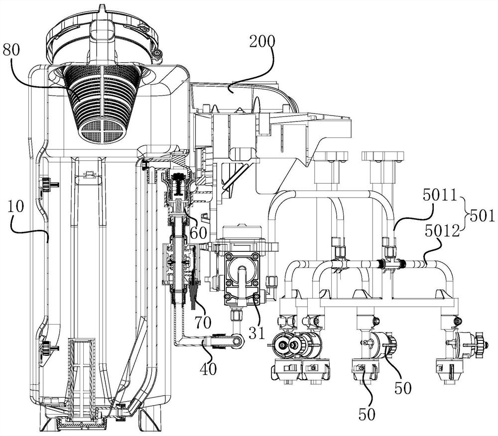
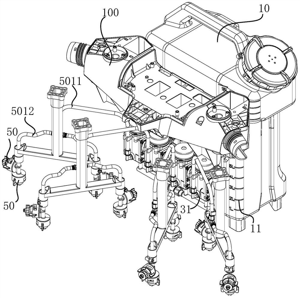
[0032] figure 1 The front view of the installation state of the sprinkler system and the rack provided by the embodiment of the present invention; figure 2 for figure 1 sectional view of image 3 The three-dimensional state diagram of the spraying system and the frame provided for the embodiment of the present invention; Figure 4 Schematic diagram of the installation of the pump set and the installation frame of the spraying system provided by the embodiment of the present invention Figure 1 ; Figure 5 Schematic diagram of the installation of the pump set and the installation frame of the spraying system provided by the embodiment of the present invention Figure II ; Figure 6 Schematic diagram of the installation of the pump set and the installation frame of the spraying system provided by the embodiment of the present invention Figure three . Please refer to Figure 1-Figure 6 , The sprinkler system 100 provided in this embodiment includes: a water tank 10 , an...

Embodiment 2

[0050] On the basis of the first embodiment, this embodiment further provides a specific installation method of the water pump 31, such as Figure 4 As shown, the first connecting portion may be the locking hole 21 , and the second connecting portion may be the locking member 311 matched with the locking hole 21 .

[0051] Specifically, the clamping hole 21 may be formed on the second mounting frame 20b, and the forming method of the clamping hole 21 may specifically be that a hole is formed on the second mounting frame 20b to form the clamping hole 21, or it may be formed on the second mounting frame 20b. Formed during integral molding, for example, the second mounting frame 20b is integrally injection molded. When designing the injection mold, a protrusion is provided at the position of the required forming hole 21. During the injection molding process, the injection material flows to the mold, and the protrusion blocks the injection molding. The material is injected to form...

Embodiment 3

[0056] This embodiment is based on the second embodiment, further, as Figure 4 and Figure 6 As shown, the clamping hole 21 may include a large hole portion 211 and a small hole portion 212 communicating with each other. The large hole portion 211 is used for inserting the holding member 311 , and the small hole portion 212 is used for mounting the holding member 311 . It can be understood that when the clamping hole 21 is formed on the second installation frame 20 b and the clamping member 311 is formed on the water pump 31 , the large hole portion 211 may be located above the small hole portion 212 . However, when the clamping hole 21 is formed on the water pump 31 and the clamping member 311 is formed on the second mounting bracket 20b, the small hole portion 212 is located above the large hole portion 211 .

[0057] Specifically, in this embodiment, since the large hole portion 211 does not need to cooperate with the holding member 311, it only needs to provide a space f...


PUM


Abstract

A spraying system (100) and an agricultural plant protection machine, comprising: a water tank (10) connected to a water distributor (40), the water distributor (40) being in communication with the water tank (10); a mounting frame 20, wherein a plurality of first connecting parts are arranged on the mounting frame (20); the pump set (30) that comprises a plurality of water pumps (31), each waterpump (31) is communicated with a corresponding water outlet in the water segregator (40), each water pump (31) is provided with a second connecting part, and the first connecting parts and the secondconnecting parts are matched to hang each water pump (31) on the mounting frame (20), and the water pump (31) is quickly and detachably connected with the mounting frame (20) through the first connecting part and the second connecting part.

Description

technical field [0001] The embodiments of the present invention relate to the technical field of agricultural plant protection spraying, in particular to a spraying system and an agricultural plant protection machine. Background technique [0002] Efficiency has always been a concern in the field of agricultural plant protection machine spraying applications such as agricultural drones, pesticide spraying vehicles, and human spraying devices. In addition to the spraying efficiency during the spraying process, once a failure occurs during the spraying process, the speed of maintenance or replacement of the spraying system will also affect the efficiency, delaying the precious time of busy farming, and in serious cases, the best time for spraying may be missed, resulting in irreparable economic loss. [0003] The plant protection drone spraying system in the prior art is not easy to disassemble. Usually, when working in the field, the spraying system occasionally breaks down,...

Claims


Application Information

Patent Timeline
Patent Type & Authority Applications(China)
IPC IPC(8): B64D1/18A01M7/00
CPCB64D1/18A01M7/005B64U2101/00A01M7/00
Inventor 舒展卢绰莹
Owner SZ DJI TECH CO LTD
Learn More