
Patsnap Eureka
For R&D, Patsnap Eureka makes reading and utilizing patents & technical documents easy.
Patsnap Eureka AIR
Designed for self-driven R&D workflows. Generate viable solutions, solve complex R&D challenges, empower your innovation with AI.

Patsnap Eureka Materials
Designed for material experts only. Revolutionize your material R&D, from search, analyze, to developing new materials.

TechResearch
Generate reliable direction feasibility study reports for your R&D in just a few steps.

TechSeek
Discover and master advanced knowledge NOW. Basics, ideas, possibilities, all at once.

TechMind
As an expert in R&D Theories, TechMind can generates customized viable solutions instantly.

TechRisk
Analyze your overall solution with one click, know your potential R&D risks in advance.

TechMonitor
Get weekly tech updates, stay abreast of the latest tech innovations and key insights.
Slab transferring device
A technology of transfer device and sheet skin, which is applied in the direction of transportation and packaging, conveyor objects, etc., can solve the problems of reduced production efficiency, unsafety, suction cup damage, etc., and achieve the effect of ensuring the quality of finished products and reducing the impact of integrity
- Summary
- Abstract
- Description
- Claims
- Application Information
AI Technical Summary
Problems solved by technology
Method used
Image

Examples
Embodiment 1
[0028] The slab running device of the present embodiment, concrete technical scheme is as follows:
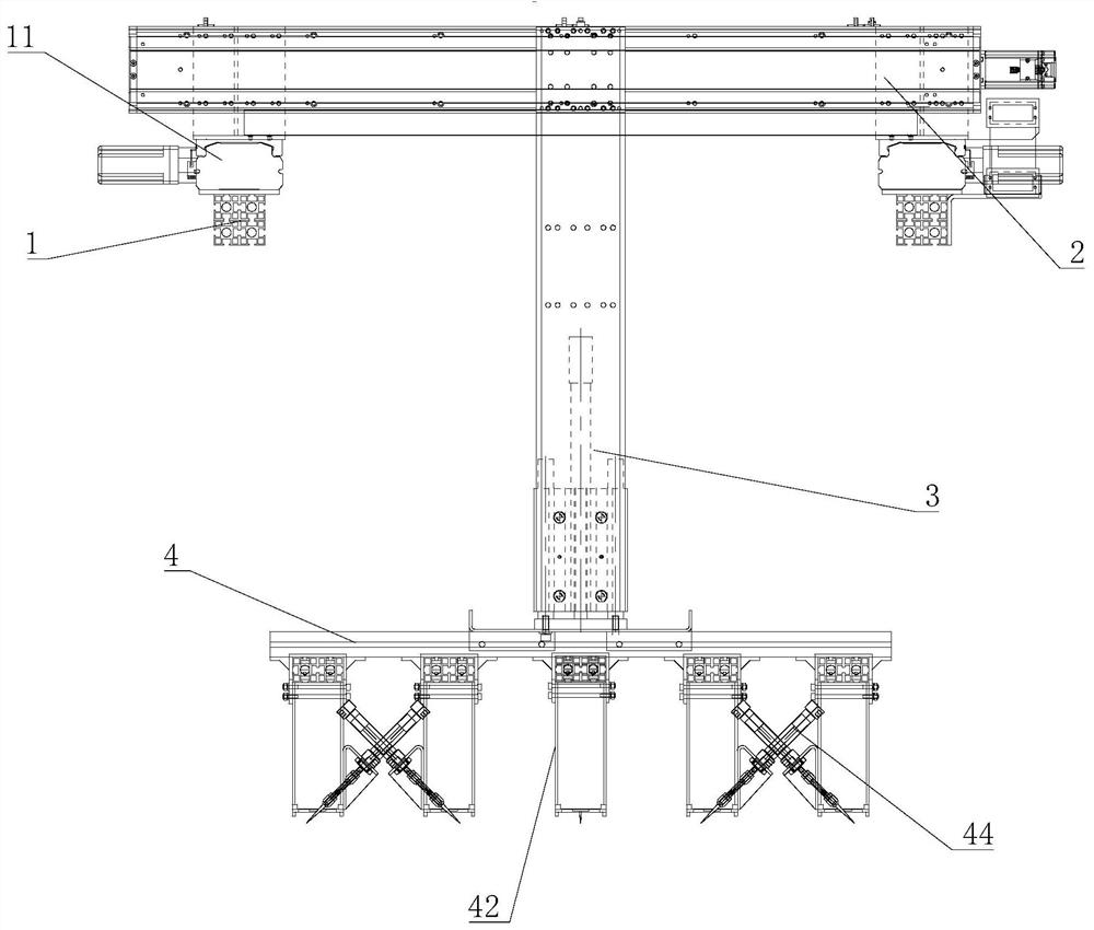
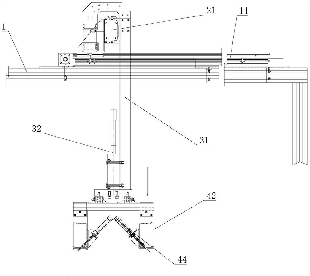
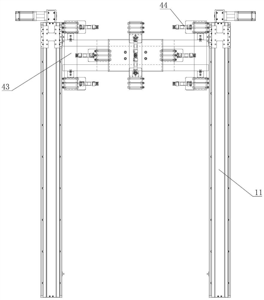
[0029] like Figure 1-3 As shown, the slab transfer device includes a bracket 1, a horizontal moving component 2 is slid on the bracket 1, and a lifting component 3 is slid on the horizontal moving component 2, and the sliding of the horizontal moving component 2 is vertical to the sliding direction of the lifting component 3 , the lifting component 3 is connected with the grabbing component 4, so that the lifting component 3, the lifting component 3 slides along the horizontal moving component 2, and the horizontal moving component 2 slides along the bracket 1 so as to realize the three-dimensional up and down, left and right and front and rear of the grabbing component 4 move. The grabbing assembly 4 includes a plurality of slab inserts 41 and a plurality of pressing sleeves 42 , and the slab inserts 41 are telescopically arranged in the pressing sleeves 42 . The pressure s...
Embodiment 2
[0036] The slab 5 operating device of the present embodiment, concrete technical scheme is as follows:
[0037] Plate skin 5 transfer device, such as Figure 6 As shown, it includes a bracket 1, a horizontal moving component 2 is slid on the bracket 1, a lifting component 3 is slid on the horizontal moving component 2, the sliding of the horizontal moving component 2 is vertical to the sliding direction of the lifting component 3, and the lifting component 3 is connected There is a grasping component 4, so through the lifting component 3, the lifting component 3 slides along the horizontal moving component 2, and the horizontal moving component 2 slides along the bracket 1 so as to realize the three-dimensional movement of the grasping component 4 up and down, left and right, and front and back. The grabbing assembly 4 includes a plurality of slab inserts 41 and a plurality of pressing sleeves 42 , and the slab inserts 41 are telescopically arranged in the pressing sleeves 42 ...
Embodiment 3
[0044] The slab 5 operating device of the present embodiment, concrete technical scheme is as follows:
[0045] Plate skin 5 transfer device, such as Figure 9 As shown, it includes a bracket 1, a horizontal moving component 2 is slid on the bracket 1, a lifting component 3 is slid on the horizontal moving component 2, the sliding of the horizontal moving component 2 is vertical to the sliding direction of the lifting component 3, and the lifting component 3 is connected There is a grasping component 4, so through the lifting component 3, the lifting component 3 slides along the horizontal moving component 2, and the horizontal moving component 2 slides along the bracket 1 so as to realize the three-dimensional movement of the grasping component 4 up and down, left and right, and front and back. The grabbing assembly 4 includes a plurality of slab inserts 41 and a plurality of pressing sleeves 42 , and the slab inserts 41 are telescopically arranged in the pressing sleeves 42 ...
PUM
 Abstract
Description
Claims
Application Information
 - R&D Engineer
- R&D Manager
- IP Professional
- Industry Leading Data Capabilities
- Powerful AI technology
- Patent DNA Extraction
Browse by: Latest US Patents, China's latest patents, Technical Efficacy Thesaurus, Application Domain, Technology Topic, Popular Technical Reports.
© 2024 PatSnap. All rights reserved.Legal|Privacy policy|Modern Slavery Act Transparency Statement|Sitemap|About US| Contact US: help@patsnap.com