Building solar panel body assembling system and method
A solar panel body and assembly system technology, applied in solar heating systems, solar thermal energy, solar thermal power generation, etc., can solve problems such as the inability to change the angle of the solar panel body, easy water ingress into the assembly bracket, and affect the use of the situation, so as to achieve firm connection The effect of tightness, tight assembly, and avoidance of water leakage
- Summary
- Abstract
- Description
- Claims
- Application Information
AI Technical Summary
Problems solved by technology
Method used
Image
Examples
Embodiment 1
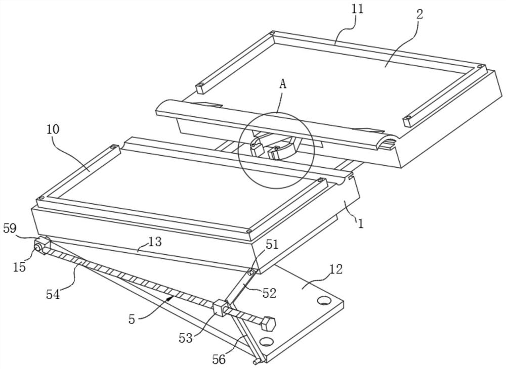
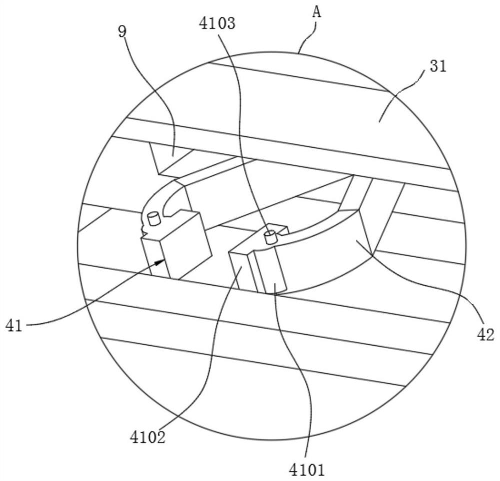
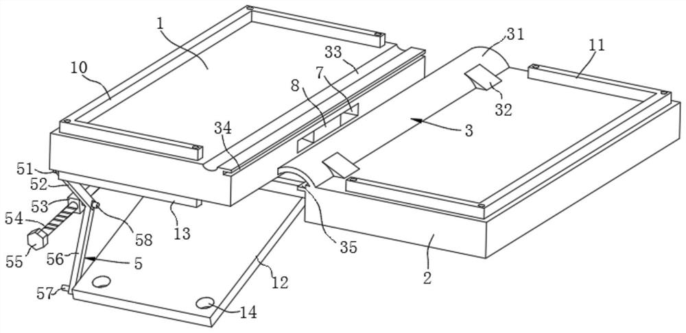
[0043] Example 1, please refer to Figure 1-6 , the present embodiment provides a technical solution: building solar panel assembly system, including assembly panel one 1, assembly panel two 2, waterproof unit 3, clamping unit 4, inclination adjustment unit 5 and sliding support unit 6;
[0044] Assembly plate one 1 and assembly plate two 2 have the same size and are arranged correspondingly on the left and right sides. Assembly plate one 1 is provided with mounting frame one 10, and mounting frame one 10 is provided with screw holes, and is connected with a solar panel body by bolts. Screw holes are also provided on the second 2, and are connected with another solar panel body by bolts. The middle part of the side of the assembly plate 1 near the assembly plate 2 2 is provided with a clamping groove 7, and the inside of the clamping groove 7 is provided with an isosceles Trapezoidal snap-in block 8, and the larger end of snap-in block 8 is outwardly arranged, and the side of ...
Embodiment 2
[0065] Example 2, please refer to Figure 7 , this embodiment provides a technical solution: building solar panel assembly system, the structural solution of this embodiment is roughly the same as that of Embodiment 1, the difference is that the transmission assembly 42 includes a scissor bar 4211 and a scissor shaft 4212 , the scissor bar 4211 is provided with two and crossed, the intersection of the two scissor bars 4211 is movably connected by the scissor shaft 4212, and the scissor shaft 4212 is fixed at the port of the installation groove 9, the two scissor bars 4211 One end protruding from the installation groove 9 is bent toward each other, and the ends of the two scissor bars 4211 are fixedly connected with the clamping movable pin 4103 .
[0066] The two scissor rods 4211 form a scissor link through the scissor shaft 4212, and the movement of the two scissor rods 4211 can drive the two clamping blocks 4102 to move toward or away from each other.
[0067]The power ass...
PUM
 Abstract
Description
Claims
Application Information
 - R&D
- Intellectual Property
- Life Sciences
- Materials
- Tech Scout
- Unparalleled Data Quality
- Higher Quality Content
- 60% Fewer Hallucinations
Browse by: Latest US Patents, China's latest patents, Technical Efficacy Thesaurus, Application Domain, Technology Topic, Popular Technical Reports.
© 2025 PatSnap. All rights reserved.Legal|Privacy policy|Modern Slavery Act Transparency Statement|Sitemap|About US| Contact US: help@patsnap.com


