
Meter reading wire connector and meter reading equipment

A meter connector and connector technology, which is applied in the field of meter reading connectors and meter reading equipment, can solve the problems of unavailable, affecting the success rate of meter reading, and reducing customer experience, so as to improve the success rate of meter reading and ensure the stability of communication Sexuality and the effect of improving customer experience

Inactive Publication Date: 2021-01-08
GUANGDONG POWER GRID CO LTD +1
View PDF7 Cites 0 Cited by
  • Summary
  • Abstract
  • Description
  • Claims
  • Application Information

AI Technical Summary

Problems solved by technology

However, the success rate of low-voltage centralized meter reading is difficult to reach 100%. One of the important reasons is the problem of the wiring method.
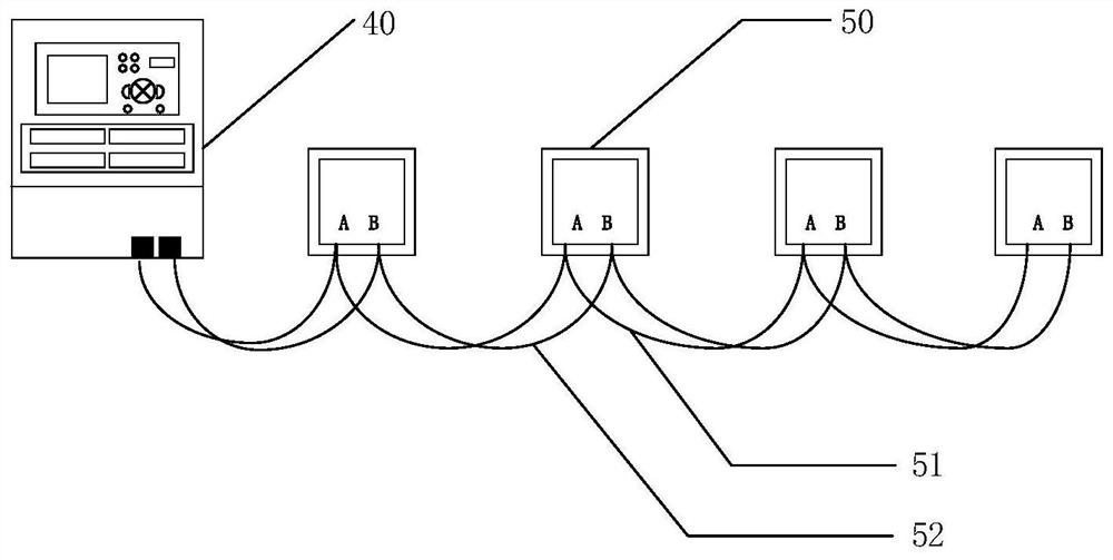
[0003] like figure 1 As shown in , the traditional method is that the 485 wires of the electric energy meter in the electric energy meter meter box are connected in a hand-in-hand manner, that is, one electric energy meter is connected to the concentrator in series with the next electric energy meter. If there is an electric energy meter in the middle If the wiring of the meter is faulty, such as a virtual connection (open circuit state), then the data of all the energy meters behind the energy meter will not be available, which seriously affects the success rate of meter reading and reduces the customer experience.

Method used


Image

  • Meter reading wire connector and meter reading equipment
  • Meter reading wire connector and meter reading equipment
  • Meter reading wire connector and meter reading equipment

Examples


Embodiment Construction

[0030] The present invention will be further described in detail below in conjunction with the accompanying drawings and embodiments. It should be understood that the specific embodiments described here are only used to explain the present invention, but not to limit the present invention. In addition, it should be noted that, for the convenience of description, only some structures related to the present invention are shown in the drawings but not all structures.

[0031] It should be noted that the terms "first" and "second" in the specification, claims and drawings of the present invention are used to distinguish different objects, rather than to limit a specific order. The following embodiments of the present invention may be implemented independently, or may be implemented in combination with each other, which is not specifically limited in the embodiments of the present invention.

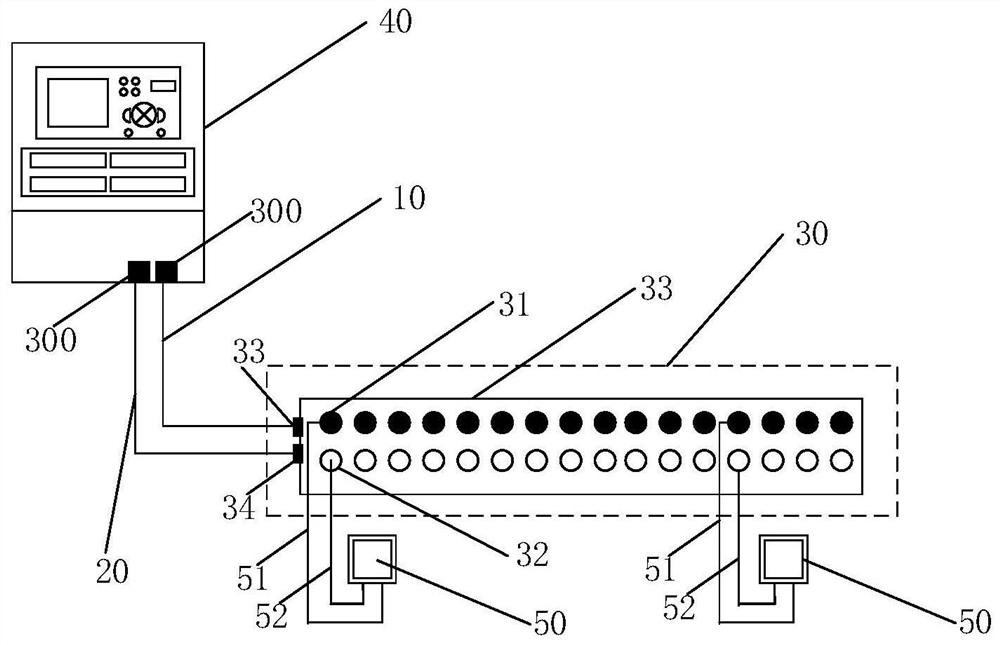
[0032] figure 2 It is a structural diagram of a meter reading connector provided by an...


PUM


Abstract

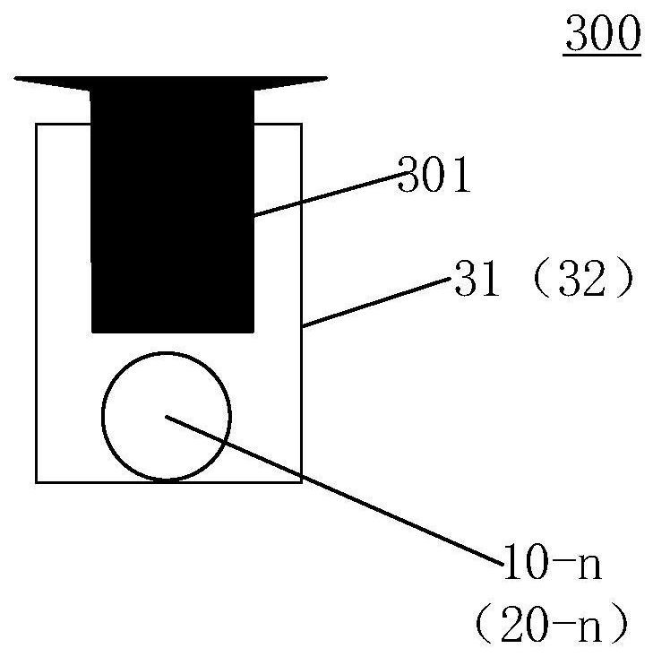
The invention discloses a meter reading wire connector and meter reading equipment. The meter reading wire connector comprises a first wiring harness, a second wiring harness and at least one 485 communication wiring device, the 485 communication wiring device is electrically connected with a concentrator through the first wiring harness and the second wiring harness; the 485 communication wiringdevice comprises a plurality of first wiring terminals and a plurality of second wiring terminals, the plurality of first wiring terminals are not communicated with each other, and the plurality of second wiring terminals are not communicated with each other; wherein the first wiring harness comprises a plurality of first twisted pairs, and the second wiring harness comprises a plurality of secondtwisted pairs; each first twisted pair is correspondingly connected with one first wiring terminal, and each second twisted pair is correspondingly connected with one second wiring terminal; and theplurality of electric energy meters are electrically connected with the 485 communication wiring device through the first wiring terminals and the second wiring terminals. According to the invention,the communication stability between the electric energy meter and a concentrator is ensured, the problem that data of all subsequent electric energy meters cannot be obtained when one electric energymeter fails is avoided, the meter reading success rate is improved, and the customer experience is improved.

Description

technical field [0001] The embodiment of the invention relates to the technical field of meter reading, in particular to a meter reading connector and meter reading equipment. Background technique [0002] Low-voltage centralized reading is usually responsible for collecting more than one million low-voltage electricity data, which plays a very important role in social and people's livelihood protection. However, the success rate of low-voltage centralized meter reading is difficult to reach 100%. One of the important reasons lies in the problem of the wiring method. [0003] Such as figure 1 As shown in , the traditional method is that the 485 wires of the electric energy meter in the electric energy meter meter box are connected in a hand-in-hand manner, that is, one electric energy meter is connected to the concentrator in series with the next electric energy meter. If there is an electric energy meter in the middle If the wiring of the meter is faulty, such as virtual ...

Claims


Application Information

Patent Timeline
IPC IPC(8): G01R22/06G01R11/04G08C19/00
CPCG01R11/04G01R22/063G01R22/066G08C19/00
Inventor 方绍怀王泉袁博政李学鹏
Owner GUANGDONG POWER GRID CO LTD
Learn More