
Liquid level control assembly

A technology of liquid level control and liquid level controller, which is applied in the direction of engine components, valve details, valve operation/release devices, etc., can solve the problems of low control precision, complicated control process, complex structure, etc., to improve control precision, High control precision and good sealing effect

Pending Publication Date: 2021-01-08
ANHUI REDSTAR VALVE
View PDF0 Cites 0 Cited by
  • Summary
  • Abstract
  • Description
  • Claims
  • Application Information

AI Technical Summary

Problems solved by technology

[0003] It can be seen that the above-mentioned liquid level control assembly not only has a complex structure, many parts, and troublesome assembly and maintenance, but also the sealing of the above-mentioned channel mainly relies on the buoyancy of the float to directly act on the differential seal. , it is necessary to increase the volume of the float and the control box, which not only increases the overall volume of the liquid level control, but also reduces the control accuracy; at the same time, the overall control of the liquid level control component needs to go through three actions to realize the liquid storage device. Supplement or stop the liquid feeding action, the control process is complicated and the control accuracy is low

Method used


Image

  • Liquid level control assembly
  • Liquid level control assembly
  • Liquid level control assembly

Examples


Embodiment Construction

[0046] The technical solutions in the embodiments of the present invention will be clearly and completely described below in conjunction with the accompanying drawings in the embodiments of the present invention. Obviously, the described embodiments are only part of the embodiments of the present invention, not all of them. Based on the implementation manners in the present invention, all other implementation manners obtained by persons of ordinary skill in the art without making creative efforts belong to the scope of protection of the present invention.

[0047] It should be noted that when a component is said to be "mounted on" another component, it may be directly mounted on another component or there may be an intervening component. When a component is said to be "set on" another component, it may be set directly on the other component or there may be an intervening component at the same time. When a component is said to be "fixed" to another component, it may be directly...


PUM


Abstract

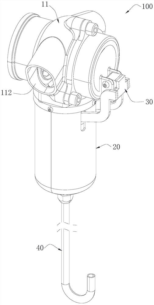
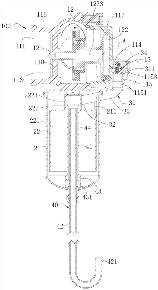
The invention relates to the technical field of valves, in particular to a liquid level control assembly. The liquid level control assembly comprises a main valve structure and a liquid level controller, and the liquid level controller is connected to the main valve structure and used for controlling opening / closing of the main valve structure; the main valve structure comprises a valve body unit,a first sealing unit and a second sealing unit; and the liquid level controller comprises a control box and a floater, the control box is connected to the valve body unit, and the floater is arrangedin the control box and can move in the control box under corresponding acting force. The liquid level control assembly further comprises a lever unit, one end of the lever unit is pivoted to the valve body unit and connected with the second sealing unit, and the other end of the lever unit extends into the control box and is connected with the floater, so that the floater subjected to corresponding acting force is capable of amplifying the acting force through the lever unit to drive the second sealing unit to act to open / close a first control hole, then the first sealing unit is controlled to move so as to control connection / disconnection between an inlet and an outlet. The liquid level control assembly has the advantages of being simple in structure and small in size.

Description

technical field [0001] The invention relates to the technical field of valves, in particular to a liquid level control assembly. Background technique [0002] The liquid level control component is installed in the liquid storage device and is mainly used to automatically control the level of the liquid in the liquid storage device. The liquid level control assembly generally includes the main valve, the liquid level controller, and the liquid level controller is connected to the main valve through the pipeline; the liquid level controller includes the valve body assembly, the diaphragm, the valve core, the differential seal control box and the float, And it is necessary to open a through hole on the disc, and open a channel communicating with the through hole on the valve core. The differential seal is installed between the control box and the valve body assembly, and the opening / closing of the channel is controlled by the buoyancy of the float. Close, so as to drive the mo...

Claims


Application Information

Patent Timeline
Patent Type & Authority Applications(China)
IPC IPC(8): F16K31/20F16K31/44
CPCF16K31/20F16K31/44
Inventor 孙世林韩安伟李维槽
Owner ANHUI REDSTAR VALVE
Learn More