A garbage transport device

A technology for conveying devices and domestic garbage, applied in trash cans, garbage collection, household utensils, etc., can solve the problems of blockage of garbage input ports, increased labor intensity, and unclean dumping, etc., to prevent blockage, facilitate collection, and facilitate disposal. Effect

Active Publication Date: 2021-08-31
兴力洁道路保洁集团有限公司
View PDF0 Cites 0 Cited by
  • Summary
  • Abstract
  • Description
  • Claims
  • Application Information

AI Technical Summary

Problems solved by technology

[0004] The purpose of the present invention is to solve the shortcomings of the prior art that do not have the function of separating liquid garbage, and the structure is simple, the collection is inconvenient, the garbage input port is easy to cause blockage, the dumping is not clean, and the shortcomings of increasing labor intensity are proposed. domestic waste conveying device

Method used


Image

  • A garbage transport device
  • A garbage transport device
  • A garbage transport device

Examples


Embodiment 1

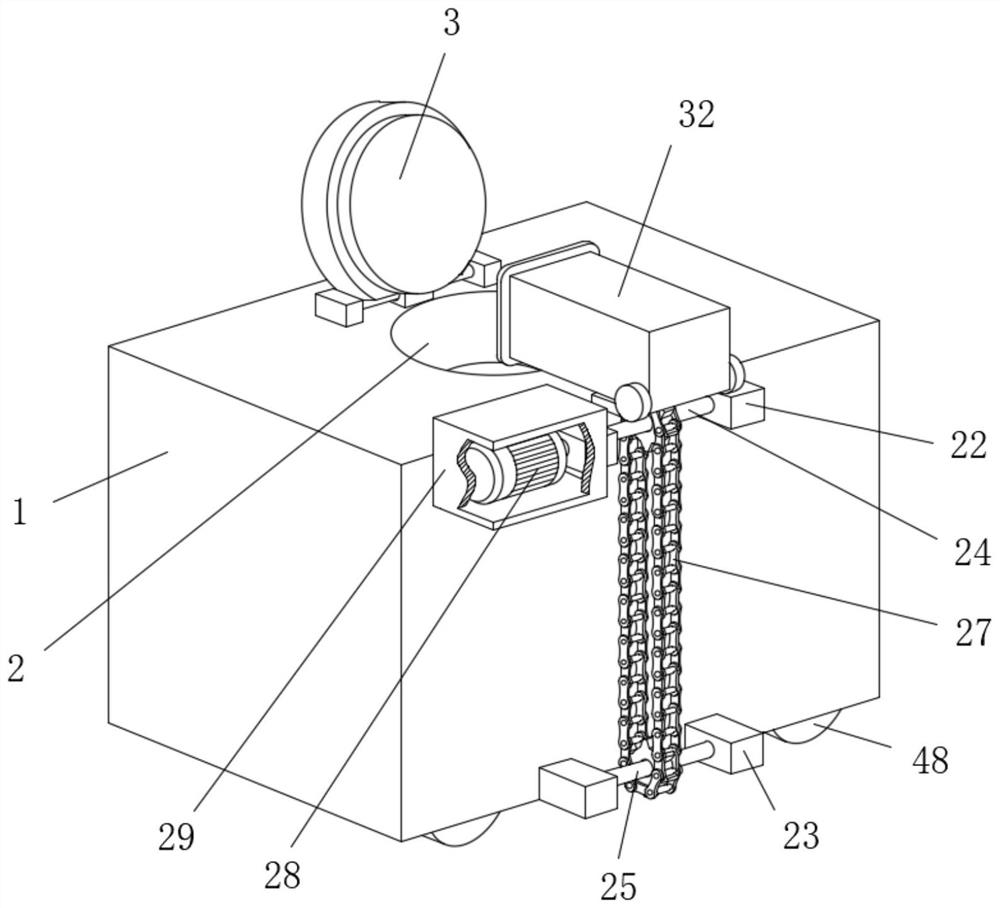
[0034] refer to Figure 1-8 , a living garbage conveying device, comprising a box body 1, the top of the box body 1 is penetrated and fixedly connected with an input bucket 2, and the top outer wall of the box body 1 is rotatably connected with a cover plate 3, and the cover plate 3 is matched with the input bucket 2, Two movable plates 6 are symmetrically slidably connected to the inner wall of the side of the box body 1 away from each other, and a first groove 7 is provided on the side where the two movable plates 6 are close to each other. In the same solid collection box 8, one side of the input bucket 2 extends to the inner wall of the box body 1 and cooperates with the solid collection box 8. Two fixed plates 14 are symmetrically fixedly connected to the inner wall of the side of the box body 1 away from each other, and the two The bottoms of the two fixing plates 14 are respectively in contact with the bottom inner wall of the box body 1, and the sides where the two fix...

Embodiment 2

[0036] Further improvement on the basis of Embodiment 1: the four corners of the movable plate 6 away from the solid collection box 8 are fixedly connected with slide bars 5, and the sides of the four slide bars 5 away from the movable plate 6 are all slidably sleeved. Sleeve 4, and one end of four sleeves 4 is fixedly connected with the inner wall of one side of box body 1 respectively, through the cooperation of sleeve 4 and slide bar 5, can play the effect of stably supporting and sliding movable plate 6, slide bar 5. One end located inside the sleeve 4 is fixedly connected with a first return spring 9, and the other end of the first return spring 9 is fixedly connected with the inner wall of one side of the sleeve 4. The first return spring 9 can act on the slide bar 5. Reset effect, the side of solid collection box 8 close to box door 47 is symmetrically fixedly connected with two first clamping columns 10, and the side of two movable plates 6 near box door 47 is all rotat...


PUM


Abstract

The invention belongs to the technical field of garbage conveying devices, in particular to a household garbage conveying device, which has no function of separating liquid garbage in the prior art, and is simple in structure, inconvenient to collect, easy to cause blockage of garbage input port, dumping is not clean, and increases For the problem of labor intensity, the following scheme is now proposed, which includes a box body. The top of the box body is fixedly connected with an input bucket, and the top outer wall of the box body is rotatably connected with a cover plate, and the cover plate is matched with the input bucket. The present invention In the process, the solid collection box can be driven to move back and forth by starting the rotating motor, which can not only achieve the effect of vibration, facilitate the flat stacking of garbage, prevent the clogging of the input bucket, but also improve the separation effect of liquid garbage, and facilitate the collection of liquid garbage. The movement of the movable plate can also drive the vibrating plate to move up and down, so as to achieve the effect of vibrating the garbage bin, thereby ensuring the effect of thorough dumping.

Description

technical field [0001] The invention relates to the technical field of garbage conveying devices, in particular to a household garbage conveying device. Background technique [0002] Garbage refers to solid waste generated by people in their daily life or activities that provide services for daily life, as well as solid waste that is regarded as domestic garbage according to laws and administrative regulations. Household garbage can generally be divided into four categories: recyclable garbage, kitchen garbage, hazardous garbage and other garbage, which mainly include household garbage, bazaar trade and commercial garbage, public place garbage, street cleaning garbage and enterprise and institution garbage. And so on, common garbage disposal methods mainly include comprehensive utilization, sanitary landfill, incineration and composting. [0003] There is no lack of liquid garbage in the current domestic garbage, and the existing garbage storage boxes and transportation box...

Claims


Application Information

Patent Timeline
Patent Type & Authority Patents(China)
IPC IPC(8): B65F1/10B65F1/12
CPCB65F1/10B65F1/12
Inventor 李鸿义黄吉祥
Owner 兴力洁道路保洁集团有限公司
Why Eureka
Try Eureka