Platform door system lookout lamp strip control device and method
A control device, platform door technology, applied in energy-saving control technology, electrical components and other directions, can solve the problem of high failure rate of the lookout light belt, achieve the effect of less difficulty in installation, simple wiring, and ensure accuracy
- Summary
- Abstract
- Description
- Claims
- Application Information
AI Technical Summary
Problems solved by technology
Method used
Image
Examples
Embodiment 1
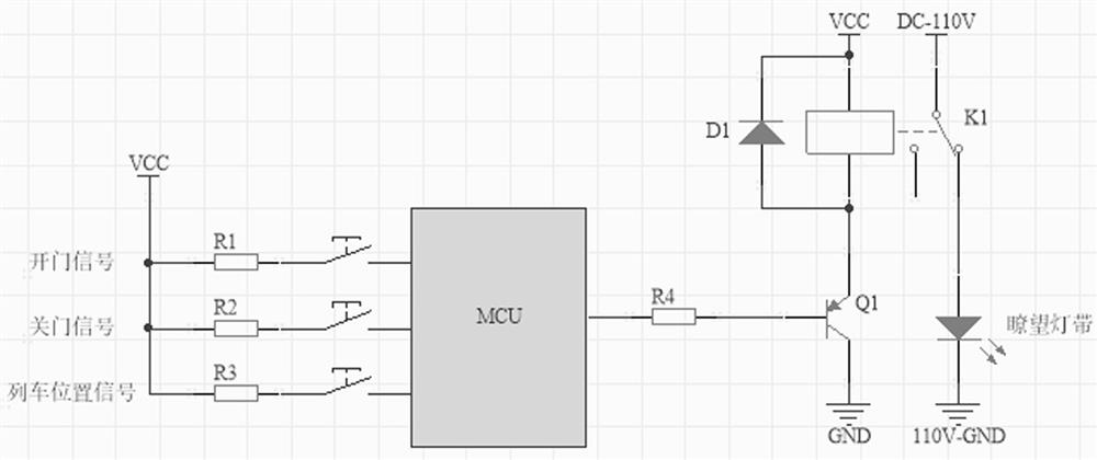
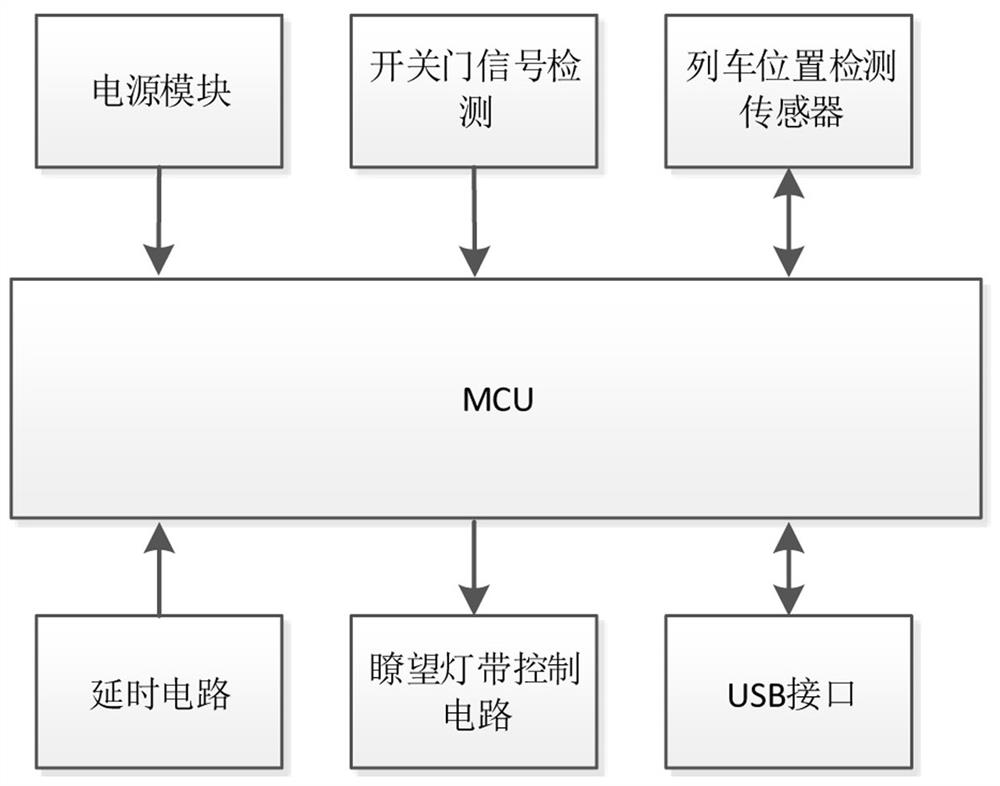
[0035] Embodiment 1: The subway platform door separates the platform from the train running area, and a lookout light strip is set on or near the end door column of the platform door for the driver to observe whether there are foreign objects between the train and the platform door. This embodiment provides a platform door system lookout light strip control device, such as figure 1 and figure 2 As shown, the device includes a power supply module, a micro control unit (MCU), a door opening and closing detection module, a train position detection sensor, a delay circuit and a lookout light strip control circuit. The train position sensor is used to obtain the train position. The reference to whether there is a foreign object between the platform door is that the lookout light strips are all on. Therefore, in order to avoid other light from affecting the lookout light strips in this embodiment, the train position sensor uses a non-contact sensor that does not produce visible and...
Embodiment 2
[0044] Embodiment 2: The similarities between this embodiment and Embodiment 1 will not be repeated. The difference is that there is a difference in the control circuit of the lookout light belt. Specifically, the switching element of this embodiment is a rheostat switch, such as Figure 6 As shown, the rheostat switch includes a gear box and a rheostat disc. The gear box includes a driving gear 4, a driven gear 5 and a composite driving gear 6. The driving gear meshes with the driven gear, and the composite driving gear and the driven gear are coaxially connected. , the rheostat plate includes the end driven gear, the end driven gear meshes with the composite driving gear, the end driven gear is provided with a carrier plate 1, the carrier plate and the end driven gear are integrally connected, and a sliding rheostat is arranged on the carrier plate , the sliding rheostat is provided with a rheostat slideway 2 and a rheostat sliding piece 3, one end of the sliding rheostat is ...
Embodiment 3
[0046] Embodiment 3: The similarities between this embodiment and Embodiment 2 will not be repeated, and the difference is that, as Figure 7 As shown, the end driven gear of the rheostat switch in this embodiment is driven by a stepping motor 8, and the stepping motor drives the carrier plate 1 to rotate forward or reverse to realize the increase or decrease of the resistance while precisely controlling the rotation In actual use, the rotation speed of the stepping motor can be controlled according to the needs to control the time when the lookout light belt is on or off. It is simple and practical, and can significantly prolong the service life of the LED light.
PUM
 Abstract
Description
Claims
Application Information
 - R&D Engineer
- R&D Manager
- IP Professional
- Industry Leading Data Capabilities
- Powerful AI technology
- Patent DNA Extraction
Browse by: Latest US Patents, China's latest patents, Technical Efficacy Thesaurus, Application Domain, Technology Topic, Popular Technical Reports.
© 2024 PatSnap. All rights reserved.Legal|Privacy policy|Modern Slavery Act Transparency Statement|Sitemap|About US| Contact US: help@patsnap.com


