
Ground assembly type wiring duct mounting structure

An installation structure and assembly technology, applied in the direction of cable installation and cable installation in ground conduits, can solve problems such as inconvenient cable troubleshooting, and achieve the effect of easy cable troubleshooting, easy troubleshooting, and beautiful structure.

Pending Publication Date: 2021-01-05
GOLD MANTIS FINE DECORATION TECH SUZHOU CO LTD
View PDF0 Cites 2 Cited by
  • Summary
  • Abstract
  • Description
  • Claims
  • Application Information

AI Technical Summary

Problems solved by technology

[0003] The existing wiring trough is usually composed of two parts: the upper cover and the base. The cables are arranged in the U-shaped wiring trough on the base. There are usually multiple cables installed in the U-shaped wiring trough at the same time, which brings inconvenience to cable troubleshooting.

Method used


Image

  • Ground assembly type wiring duct mounting structure
  • Ground assembly type wiring duct mounting structure
  • Ground assembly type wiring duct mounting structure

Examples


Embodiment 1

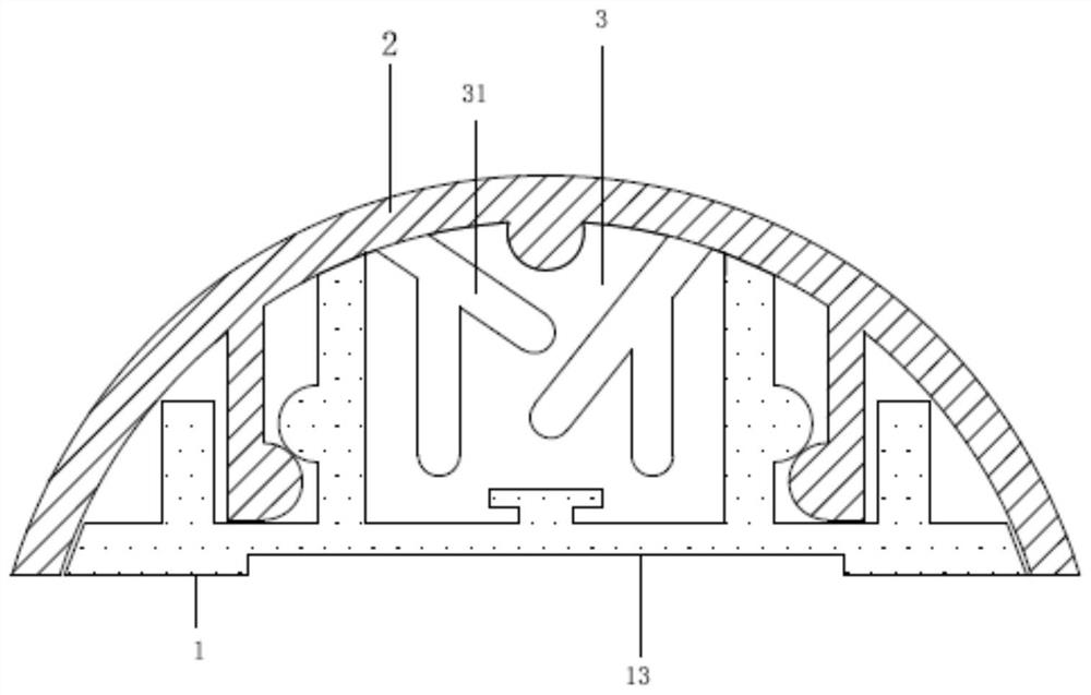
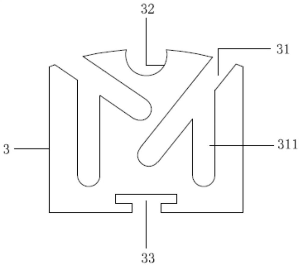
[0021] see Figure 1 to Figure 3 , the figure shows a ground-mounted wiring trough installation structure provided by Embodiment 1 of the present invention, including a base 1 and a cover plate 2, the base 1 is fixedly installed on the ground, and the base 1 is provided with a U-shaped wiring trough 11. The U-shaped threading groove 11 is provided with a plurality of partitions 3 arranged in parallel along its own length direction. The partitions 3 are provided with a plurality of notches 31 extending from the top edge to the inside, and the two ends of the cover plate 2 are arranged symmetrically. The buckle 21, the buckle 21 is fastened in the buckle groove 12 on the base.

[0022] Specifically, see Figure 1 to Figure 3 , the bottom surface of the base 1 is provided with a second groove 13 .

[0023] Specifically, see Figure 1 to Figure 3 , The partition 3 is detachably installed on the base 1 .

[0024] Specifically, see Figure 1 to Figure 3 The base 1 is provided w...

Embodiment 2

[0028] see Figure 1 to Figure 3 , the figure shows a ground-mounted wiring trough installation structure provided by Embodiment 2 of the present invention. On the basis of the above embodiment, this embodiment further makes the following technical solutions as improvements: cover plate 2 Ribs 22 arranged along the lengthwise direction are arranged on the inner side, and first grooves 32 corresponding to the ribs 22 are arranged on the separator 3 .

[0029] The inner side of the cover is provided with ribs to enhance its structural strength. The ribs are snapped into the first groove on the partition, on the one hand to ensure the assembly accuracy of the wiring trough, and on the other hand to use the partition to provide support for the cover .

Embodiment 3

[0031] see Figure 1 to Figure 3 , the figure shows a ground-mounted wiring trough installation structure provided by Embodiment 3 of the present invention. On the basis of the above embodiments, this embodiment further makes the following technical solutions as improvements: the notch 31 is inclined Setting; the notch 31 includes at least one branch notch 311 .


PUM


Abstract

The invention provides a ground assembly type wiring duct mounting structure, and the structure comprises a base and a cover plate; the base is fixedly installed on the ground, a U-shaped wiring ductis formed in the base, a plurality of partition plates arranged in parallel in the length direction of the U-shaped wiring duct are arranged in the U-shaped wiring duct, and a plurality of notches extending inwards from the top edge are formed in the partition plates; two ends of the cover plate are provided with buckles which are symmetrically arranged, and the buckles are buckled in buckling grooves in the base. According to the ground assembly type wiring duct mounting structure, independent wiring of multiple cables is achieved through the detachable partition plates in the U-shaped wiringduct, and cable troubleshooting is facilitated.

Description

technical field [0001] The invention relates to a wiring trough structure, in particular to a ground-mounted wiring trough installation structure. Background technique [0002] In the existing ground cable wiring construction, wire troughs are often used for safe wiring, that is, cables are threaded into the wire troughs, and the wire troughs are fixed on the ground to meet the ground safety wiring requirements. [0003] The existing wiring trough is usually composed of two parts, the upper cover and the base. The cables are arranged in the U-shaped threading trough on the base. There are usually multiple cables in the U-shaped threading trough at the same time, which brings inconvenience to cable troubleshooting. . Contents of the invention [0004] In view of this, the present invention provides a ground-mounted wiring trough installation structure, which solves the inconvenience of troubleshooting caused by simultaneously installing multiple cables in the U-shaped wiri...

Claims


Application Information

Patent Timeline
IPC IPC(8): H02G9/04
CPCH02G9/04
Inventor 迟玉华吴艳阳赵士勇张学应张羽史佳兴
Owner GOLD MANTIS FINE DECORATION TECH SUZHOU CO LTD
Learn More