Multi-layer rotary combined type computer wire fixing device

A computer and cable fixing technology, applied in the field of multi-layer rotary combined computer cable fixing device, can solve the problems of high labor intensity, chaotic cables, long time consumption, etc., and achieve the effects of easy maintenance, low cost and firm connection

Pending Publication Date: 2021-01-05
KAIFENG UNIV
View PDF11 Cites 0 Cited by
  • Summary
  • Abstract
  • Description
  • Claims
  • Application Information

AI Technical Summary

Problems solved by technology

[0003] The existing cable fixer structure adopts a multi-layer stacked structure, and the multi-layer cable fixing plates are stacked to realize the layering of cables and facilitate the expansion of the fixed number of cables; but this kind of cable fixer generally uses screws and bolts Cooperate with the unified fixation, and fix all the fixing plates together uniformly. In the event of overhaul, maintenance, or failure, if the staff removes the bolts and screws of the wire fixing device after determining the faulty cable, it will cause all the wire fixing plates on the wire fixing device. The confusion of the cables, after the completion of the maintenance work, it is necessary to re-sort and fix a large number of cables and all the wire fixing devices, which is difficult, labor-intensive, time-consuming, and huge losses

Method used


Image

  • Multi-layer rotary combined type computer wire fixing device
  • Multi-layer rotary combined type computer wire fixing device
  • Multi-layer rotary combined type computer wire fixing device

Examples


Embodiment Construction

[0024] The following will clearly and completely describe the technical solutions in the embodiments of the present invention with reference to the accompanying drawings in the embodiments of the present invention. Obviously, the described embodiments are only some, not all, embodiments of the present invention. Based on the embodiments of the present invention, all other embodiments obtained by persons of ordinary skill in the art without making creative efforts belong to the protection scope of the present invention.

[0025] In describing the present invention, it should be understood that the terms "middle", "length", "width", "thickness", "upper", "lower", "front", "rear", "left", " The orientation or positional relationship indicated by "right", "vertical", "horizontal", "top", "bottom", "inner", "outer", etc. is based on the orientation or positional relationship shown in the drawings, and is only for the convenience of description The present invention and simplified d...


PUM


Abstract

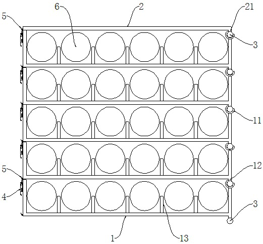
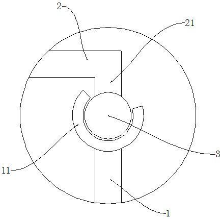
The invention discloses a multi-layer rotary combined type computer wire fixing device which comprises a plurality of turnover page plates and a cover plate. The turnover page plates are of a U-shapedplate-shaped structure, a hinge base is arranged on the edge of one end of the turnover page plates and is of a tubular structure with the arc-shaped cross section, a first protrusion is arranged onthe outer side of the corner of the same end of the turnover page plates and the hinge base, a second protrusion is vertically arranged at one end of the cover plate, and the first protrusion and thesecond protrusion are fixedly connected with cylinders. The cylinder penetrates into the hinge base from one end of the hinge base, an annular groove is formed in the middle of the cylinder, a bolt isin threaded connection with the side wall of the middle of the hinge base, the inner end of the bolt corresponds to the annular groove, a spring hasp is arranged at the end, away from the hinge base,of the turnover hinge plate, and hooks matched with the spring hasp are arranged at one end of the turnover page plates. According to the invention, various cables are layered and grouped, the assembly is simple, the expansion is convenient, a book-shaped turnover structure is provided, the cables can be turned over layer by layer like pages, and the cables are convenient to overhaul and replace.

Description

technical field [0001] The invention belongs to the technical field of computer cable fixing equipment, and in particular relates to a multi-layer rotary combined computer cable fixing device. Background technique [0002] In many traditional computer rooms, the cables are laid randomly or fixed with cable ties, tapes, etc. The cabinets in the computer room are very messy, and daily maintenance is very inconvenient. When the number of cables increases, data lines, power lines, AC lines, and DC lines are mixed, cables are twisted and knotted, heat dissipation is poor, and fire hazards are great. It is far away from high-speed transmission and high-standard computer room construction. In order to solve the above problems, those skilled in the art have developed a cable fixing device, which separates and fixes the cables in the computer room, and fixes the computer cables on the cable rack through the cable fixing device. [0003] The existing cable fixer structure adopts a mu...

Claims


Application Information

Patent Timeline
Patent Type & Authority Applications(China)
IPC IPC(8): H02G3/02
CPCH02G3/02
Inventor 沈二波庄晶旭
Owner KAIFENG UNIV
Why Eureka
Try Eureka