Lamp fixing device

A technology for fixing devices and lamps, which is applied in the direction of lighting devices, lighting auxiliary devices, components of lighting devices, etc., to achieve the effect of solving the inconvenience of disassembly

Active Publication Date: 2021-01-05
PANASONIC INTELLECTUAL PROPERTY MANAGEMENT CO LTD
View PDF9 Cites 1 Cited by
  • Summary
  • Abstract
  • Description
  • Claims
  • Application Information

AI Technical Summary

Problems solved by technology

[0005] The present invention is proposed in order to solve the above-mentioned technical problems, and the purpose is to provide a lamp fixing device, which can solve the problem that it is difficult for the existing lamp fixing device to simultaneously push each protrusion to a position where it can be rotated out

Method used


Image

  • Lamp fixing device
  • Lamp fixing device
  • Lamp fixing device

Examples


Embodiment Construction

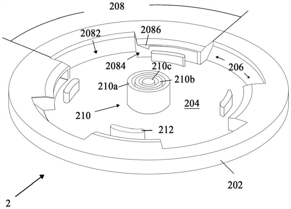
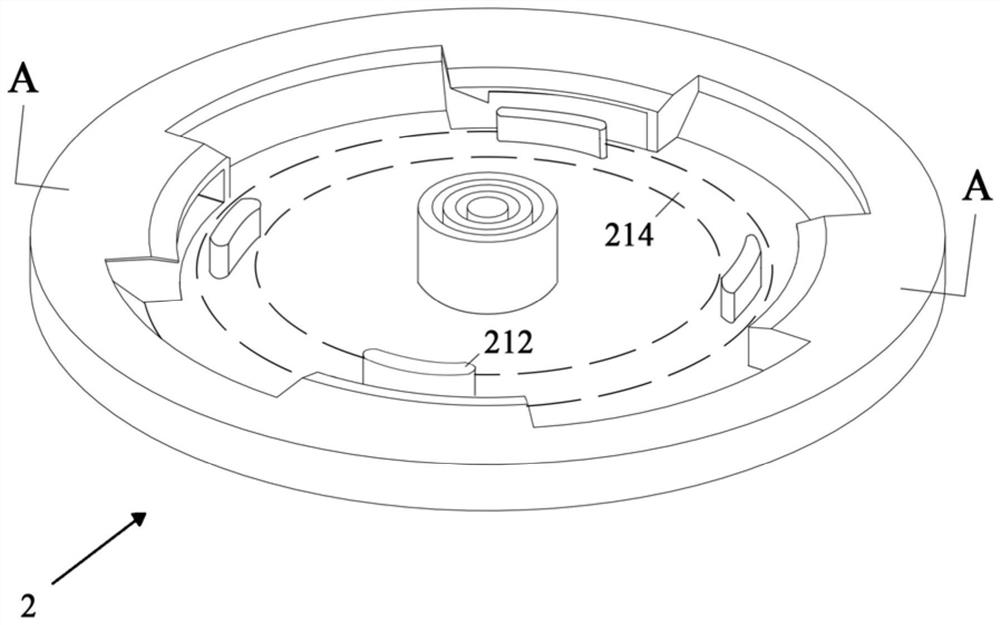
[0021] Below, while referring to the attached Figure 1 Preferred embodiments of the present invention will be roughly described. In addition, the embodiments of the present invention are not limited to the following embodiments, and various embodiments within the scope of the technical idea of ​​the present invention can be employed.

[0022] It should be noted that, in this document, the term "A presses against B in the circumferential direction" may mean that A is formed with an integral circumferentially extending plane or ejector (for example, A may be an annular plane), through which A plane or ejector extending along the circumferential direction forms abutment against B; or, A may also be formed with a plurality of discrete ejectors, which form abutment against B through a plurality of ejectors.

[0023] The lamp fixing device of this embodiment includes a fixing base 1 and a connecting base 2 that are used in cooperation with each other. Among them, such as figure ...


PUM


Abstract

The invention relates to the field of lighting devices, and provides a lamp mounting device. According to the lamp fixing device, ejecting objects located at different circumferential positions are arranged to abut against the same hard plate, so that when a user pushes a connecting base upwards, even though stress at the different positions of the connecting base is uneven, various protruding blocks can still keep the same axial displacement, the protruding blocks can be conveniently screwed out of mounting grooves at the same time, and the problem that a lamp is inconvenient to disassemble is solved.

Description

technical field [0001] The invention relates to the field of lighting equipment, and more specifically, the invention relates to a fixing device for a lamp. Background technique [0002] Lighting equipment needs to be installed on the ceiling of the room through lamp fixtures. The existing lamp fixing device adopts a separate fixing seat and connecting seat to fix the lamp, wherein the fixing seat is connected to the wall, and the connecting seat is connected to the lamp. Through the mechanical connection and electrical connection between the fixing seat and the connecting seat, the lamp is installed on the on the ceiling. [0003] In order to make the mechanical connection between the fixing base and the connecting base more stable in the existing lamp fixing device, it is necessary to use the hooking part to keep the protrusion in the installation groove. However, when disassembling the lamp fixing device, the user needs to push up the lamp and the connecting seat first,...

Claims


Application Information

Patent Timeline
Patent Type & Authority Applications(China)
IPC IPC(8): F21V21/02F21V21/04F21V23/06F21V21/002
CPCF21V21/02F21V21/044F21V21/002F21V23/06
Inventor 陈辉八田和洋戴忻王鑫
Owner PANASONIC INTELLECTUAL PROPERTY MANAGEMENT CO LTD
Why Eureka
Try Eureka