Lifting device for cable erection

A lifting device and cable technology, which is applied in the direction of lifting devices, overhead lines/cable equipment, etc., can solve the problems that the lifting device cannot be adapted to the installation, has low safety and usability, and cannot adjust the installation angle, so as to facilitate the adjustment of the installation angle and improve Effects of safe usability and improved usability

Active Publication Date: 2021-01-05
国网河南省电力公司唐河县供电公司
View PDF17 Cites 5 Cited by
  • Summary
  • Abstract
  • Description
  • Claims
  • Application Information

AI Technical Summary

Problems solved by technology

[0003] For example, the equipment cable lifting device disclosed in the utility model with the authorized announcement number CN204243706U, although it realizes that the pulling and winding can be carried out synchronously with the lifting of the lifting rod, the structure is simple, easy to operate, and has good stability, which can be adapted to The effect of the field working environment, but it does not solve the problem that the existing lifting device is easy to fall during the erection process, the stability of the device is poor, the safety of the device is low, and the connection length between the stabilizer and the ground cannot be adjusted , the installation angle cannot be adjusted, so that the lifting device cannot be adapted to the installation in different environments; and the worm on the device is easy to be touched to make it rotate when it does not need to rotate, which will have a certain adverse effect on the operating effect of the lifting device problem, for which we propose a lifting device for cable erection

Method used


Image

  • Lifting device for cable erection
  • Lifting device for cable erection
  • Lifting device for cable erection

Examples


Embodiment Construction

[0024] The following will clearly and completely describe the technical solutions in the embodiments of the present invention with reference to the accompanying drawings in the embodiments of the present invention. Obviously, the described embodiments are only some, not all, embodiments of the present invention. Based on the embodiments of the present invention, all other embodiments obtained by persons of ordinary skill in the art without making creative efforts belong to the protection scope of the present invention.

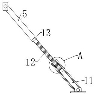
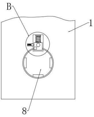
[0025] see Figure 1-Figure 5 , the present invention provides a technical solution: a lifting device for cable erection, including a lifting device main body 1, two sets of stabilizing rods 5 are symmetrically arranged on the surface of the lifting device main body 1, and one end of the stabilizing rod 5 is fixedly connected with the lifting device main body 1, stabilizing The other end of the rod 5 is rotatably connected with a second threaded rod 12 through...


PUM


Abstract

The invention discloses a lifting device for cable erection. The lifting device for cable erection comprises a lifting device main body, two groups of stabilizing rods are symmetrically arranged on the surface of the lifting device main body, and one end of each stabilizing rod is fixedly connected with the lifting device main body. Through the arrangement of the stabilizing rods, a second threaded rod and a sleeve, the situation that the device is prone to toppling over in the cable erecting process of the lifting device is effectively avoided, a certain supporting effect is achieved, the stability of the device is guaranteed, and the safe usability of the device is greatly improved. Meanwhile, the problems that the connecting length of the sleeve and the second threaded rod from the ground cannot be adjusted in the using process, and installation is inconvenient are effectively avoided. The installation angle can be adjusted easily, and the convenient usability of the lifting devicein different environments is greatly improved. Through an arranged clamping block, the situation that when a worm on the device does not need to rotate, the worm is easily touched to rotate is effectively avoided. A certain protection effect for the worm is achieved, and the operation effect of the lifting device is guaranteed.

Description

technical field [0001] The invention belongs to the technical field of lifting devices, and in particular relates to a lifting device for cable erection. Background technique [0002] A cable is an electrical energy or signal transmission device, usually composed of several or several groups of wires. Cables include power cables, control cables, compensation cables, shielded cables, high-temperature cables, computer cables, signal cables, coaxial cables, fire-resistant cables, marine cables, mining cables, aluminum alloy cables, etc. They are all composed of single or multi-strand wires and insulation layers, and are used to connect circuits, electrical appliances, etc. The manufacture of wire and cable is completely different from the production of most electromechanical products. Mechanical and electrical products are usually assembled into components, and multiple components are assembled into a single product, and the product is measured by the number of units or piece...

Claims


Application Information

Patent Timeline
Patent Type & Authority Applications(China)
IPC IPC(8): B66F3/18H02G1/04
CPCB66F3/18H02G1/04
Inventor 杨鹏宇刘松峰李晓阳陈慎
Owner 国网河南省电力公司唐河县供电公司
Why Eureka
Try Eureka