
Hobbing clamp for intermediate shaft

A hobbing fixture and intermediate shaft technology, which is applied in the field of lathe clamping devices, can solve the problems of reducing the processing efficiency of intermediate shaft gears, and long time for top inspection and replacement, so as to improve processing efficiency and improve the efficiency of inspection and replacement Effect

Pending Publication Date: 2021-01-05
重庆蓝黛传动机械有限公司
View PDF8 Cites 1 Cited by
  • Summary
  • Abstract
  • Description
  • Claims
  • Application Information

AI Technical Summary

Problems solved by technology

[0004] The purpose of the present invention is to overcome the problem in the prior art that the top of the intermediate shaft hobbing fixture is installed inside the fixture and fixed by bolts, so that the maintenance and replacement of the top takes a long time and reduces the processing efficiency of the intermediate shaft gear. Provide A gear hobbing fixture for an intermediate shaft

Method used


Image

  • Hobbing clamp for intermediate shaft
  • Hobbing clamp for intermediate shaft
  • Hobbing clamp for intermediate shaft

Examples


Embodiment 1

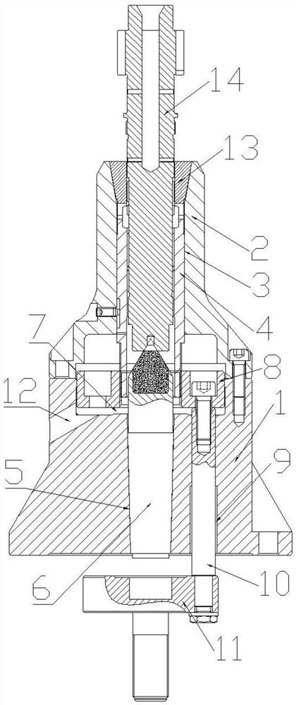
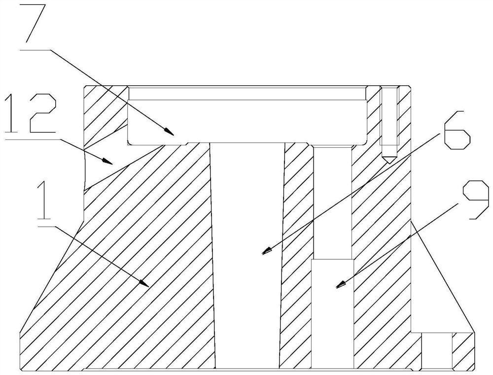
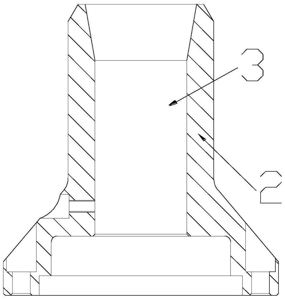
[0022] Such as Figure 1-Figure 5 As shown, a hobbing fixture for an intermediate shaft includes a base 1 and a chuck seat 2, the base 1 and the chuck seat 2 are detachably connected, and the chuck seat 2 is provided with a through hole 3, An installation sleeve 4 is slidably arranged in the through hole 3, and an elastic sleeve 13 is fixed on the end of the installation sleeve 4 away from the base 1. There is a mounting hole 5, the mounting hole 5 is in the shape of an inverted "eight", and a top 6 is arranged in the mounting hole 5, and the top 6 is provided with a mounting hole 5 adapted to the inverted "eight" shape. Slope, the top 6 is fixed to the mounting hole 5 by expansion, the base 1 is provided with a groove 7 on the side connected to the chuck seat 2, and a connecting seat 8 is arranged in the groove 7, so The connection seat 8 is fixedly connected with the installation sleeve 4, and the base 1 is also provided with a pull rod hole 9, and a pull rod 10 is arranged...


PUM


Abstract

The invention relates to a clamping device of a lathe, and particularly relates to a hobbing clamp for an intermediate shaft. The hobbing clamp comprises a base and a chuck seat, wherein the base is detachably connected with the chuck seat; a through hole is formed in the chuck seat; a mounting sleeve is arranged in the through hole; an elastic sleeve is fixed at one end of the mounting sleeve andadopts a structure with a large upper part and a small lower part; a mounting hole is formed in the base; a tip is arranged in the mounting hole and fixed with the mounting hole in an expansion manner; a groove is formed in one side, connected with the chuck seat, of the base; a connecting seat is arranged in the groove; a pull rod hole is further formed in the base; a pull rod is arranged in thepull rod hole; one end of the pull rod is fixed with the connecting seat; and an avoidance space allowing the connecting seat to move back and forth along the axis of the mounting hole is formed in the groove. The base is not required to be dismounted from the lathe, so that the tip maintenance and replacement efficiency is improved, and the intermediate shaft gear machining efficiency is furtherimproved.

Description

technical field [0001] The invention relates to a clamping device of a lathe, in particular to a hobbing fixture of an intermediate shaft. Background technique [0002] With the continuous development of society, all walks of life are advancing by leaps and bounds. The intermediate shaft is an indispensable part of the automobile gearbox. A gear is integrally arranged on the intermediate shaft. The gear is processed by a hobbing tool. Before processing the gear of the intermediate shaft, the intermediate shaft needs to be fixed on the lathe. Clamp and position the intermediate shaft. [0003] Before the gear machining of the existing intermediate shaft, the positioning of the intermediate shaft is usually achieved by matching the top end with the center hole of the end face of the intermediate shaft, and the intermediate shaft is clamped by the elastic sleeve on the fixture. Due to the traditional intermediate shaft hobbing fixture The top is fixed inside the fixture by bo...

Claims


Application Information

Patent Timeline
IPC IPC(8): B23F23/06
CPCB23F23/06
Inventor 杨芳郭耀龙陶中将曾忠红何燕
Owner 重庆蓝黛传动机械有限公司
Learn More