
Permanent magnet auxiliary synchronous reluctance motor for electric automobile

An auxiliary synchronous and electric vehicle technology, applied in electric vehicles, synchronous machines, synchronous machine parts, etc., can solve the problems of narrow high-speed field-weakening constant power range, low motor efficiency and power density, and large torque ripple. Improve the anti-demagnetization ability at low temperature, increase the volume of the accommodating groove, and reduce the effect of torque ripple

Active Publication Date: 2020-12-29
ZHEJIANG LEAPMOTOR TECH CO LTD
View PDF10 Cites 0 Cited by
  • Summary
  • Abstract
  • Description
  • Claims
  • Application Information

AI Technical Summary

Problems solved by technology

[0004] The present invention mainly solves the problems of large torque pulsation, narrow high-speed weak magnetic constant power range, and low motor efficiency and power density in the permanent magnet assisted synchronous reluctance motor in the prior art, and provides a permanent magnet assisted synchronous reluctance motor for electric vehicles. reluctance motor

Method used


Image

  • Permanent magnet auxiliary synchronous reluctance motor for electric automobile
  • Permanent magnet auxiliary synchronous reluctance motor for electric automobile

Examples


Embodiment

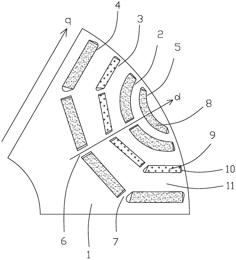
[0024] In this embodiment, a permanent magnet assisted synchronous reluctance motor for an electric vehicle, such as figure 1 As shown, the rotor core 1 is included, and a plurality of magnetic barrier groups are arranged axially on the rotor core, and the magnetic barrier groups include outer magnetic barriers 5, first magnetic barriers 2, The second magnetic barrier 3 and the third magnetic barrier 4,

[0025] The outer magnetic barrier is not provided with a partition. The first magnetic barrier is provided with a middle partition 6 , which separates the first magnetic barrier to form two accommodating grooves 10 . The second magnetic barrier and the third magnetic barrier are respectively provided with a middle partition 6 and side partitions 7 on both sides, which divide the third magnetic barrier and the fourth magnetic barrier into four accommodating slots 10 . The middle partitions of the first magnetic barrier, the second magnetic barrier and the third magnetic barr...


PUM


Abstract

The invention discloses a permanent magnet auxiliary synchronous reluctance motor for an electric automobile. The problems that in the prior art, a permanent magnet auxiliary synchronous reluctance motor is large in torque pulsation, narrow in high-speed flux-weakening constant power range and low in motor efficiency and power density are solved. The motor comprises a rotor core, a plurality of magnetic barrier groups are arranged on the rotor core, each magnetic barrier group comprises a first magnetic barrier, a second magnetic barrier and a third magnetic barrier which are arranged at intervals along a d axis, the first magnetic barrier is divided into two accommodating grooves through a middle partition part, and the second magnetic barrier and the third magnetic barrier are respectively divided into four accommodating grooves through side partition parts of the middle partition part. Ferrite is arranged in the first magnetic barrier and the third magnetic barrier, and a rare earthpermanent magnet is arranged in the second magnetic barrier. According to the invention, the motor power density and the motor efficiency are improved, and the high flux-weakening constant power range of the motor is greatly improved. The ferrite and the rare earth permanent magnet are mixed for use, so that the low-temperature demagnetization resistance of the ferrite is greatly improved, the magnetic density distribution is improved, and the torque pulsation is reduced.

Description

technical field [0001] The invention relates to the technical field of synchronous motors, in particular to a permanent magnet assisted synchronous reluctance motor for electric vehicles. Background technique [0002] At present, permanent magnet synchronous reluctance motors are more and more widely used, but the commonly used rare earth permanent magnets are very expensive, accounting for about 50% of the raw material cost of the entire motor. The torque is reduced, the corresponding amount of permanent magnet magnetic steel is also reduced, and the permanent magnet cost of the motor is also reduced. Therefore, it is a future trend to develop synchronous reluctance motors with less rare earth or even no rare earth permanent magnet auxiliary. [0003] In order to pursue a higher saliency ratio, the current permanent magnet assisted synchronous reluctance motor usually involves a multi-layer magnetic barrier structure, and permanent magnets or ferrite are inserted into the m...

Claims


Application Information

Patent Timeline
Patent Type & Authority Applications(China)
IPC IPC(8): H02K1/27H02K1/02H02K21/02
CPCH02K1/27H02K1/2766H02K1/02H02K21/028H02K2213/03Y02T10/64
Inventor 梁飞飞岳卫东汤卫平刘强巫存
Owner ZHEJIANG LEAPMOTOR TECH CO LTD
Learn More